Lexus ES: Components
Lexus ES (XZ10) Service Manual / Engine & Hybrid System / 2gr-fks (lubrication) / Oil Pump / Components
COMPONENTS
ILLUSTRATION
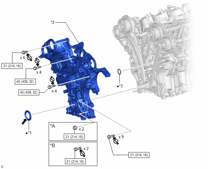
| *A | w/ Stud Bolt | *B | w/o Stud Bolt |
| *1 | TIMING CHAIN CASE OIL SEAL | *2 | TIMING CHAIN COVER ASSEMBLY |
| *3 | OIL PUMP GASKET | - | - |
.png) | N*m (kgf*cm, ft.*lbf): Specified torque | ● | Non-reusable part |
.png) | MP Grease | .png) | Do not apply lubricants to the threaded parts |
ILLUSTRATION
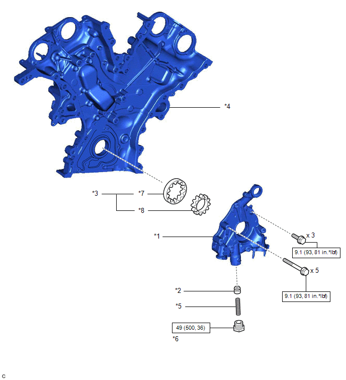
| *1 | OIL PUMP COVER | *2 | OIL PUMP RELIEF VALVE |
| *3 | OIL PUMP ROTOR SET | *4 | TIMING CHAIN COVER ASSEMBLY |
| *5 | OIL PUMP RELIEF VALVE SPRING | *6 | OIL PUMP RELIEF VALVE PLUG |
| *7 | DRIVEN ROTOR | *8 | DRIVE ROTOR |
| | N*m (kgf*cm, ft.*lbf): Specified torque | - | - |
READ NEXT:
 Removal
REMOVAL CAUTION / NOTICE / HINT The necessary procedures (adjustment, calibration, initialization or registration) that must be performed after parts are removed and installed, or replaced during timi
Disassembly
DISASSEMBLY PROCEDURE 1. REMOVE OIL PUMP RELIEF VALVE (a) Using a 27 mm socket wrench, remove the oil pump relief valve plug from the oil pump cover. (b) Remove the oil pump relief valv
Inspection
INSPECTION PROCEDURE 1. INSPECT OIL PUMP RELIEF VALVE (a) Coat the oil pump relief valve with engine oil and check that it falls smoothly into the valve hole by its own weight. HINT: If the oil pum
SEE MORE:
Door Mirror ECU RH Communication Stop Mode
DESCRIPTION Detection Item Symptom Trouble Area Door Mirror ECU RH Communication Stop Mode Any of the following conditions are met:
Communication stop for "Front Door RH/R-Mirror (FR-Door/R-Mirror)" is indicated on the "Communication Bus Check" screen of the Techstream.
Click here
Key-off Operation Function Operates even if Operating Conditions are not Satisfied
DESCRIPTION The sliding roof ECU (sliding roof drive gear sub-assembly) operates its built-in motor according to the sliding roof switch (map light sub-assembly) operation. Using the sliding roof switch (map light sub-assembly), if the sliding roof can be operated normally when 45 seconds or more ha
© 2016-2026 Copyright www.lexguide.net
