Lexus ES: Installation
INSTALLATION
PROCEDURE
1. INSTALL HEATED OXYGEN SENSOR (for Bank 2)
Click here .gif)
2. INSTALL HEATED OXYGEN SENSOR (for Bank 1)
Click here
3. INSTALL FRONT EXHAUST PIPE ASSEMBLY (TWC: Rear Catalyst)
(a) Install 2 new gaskets to the front exhaust pipe assembly (TWC: Rear Catalyst).
(b) Connect the front exhaust pipe assembly (TWC: Rear Catalyst) to the exhaust pipe support.
(c) Install the front exhaust pipe assembly (TWC: Rear Catalyst) to the exhaust manifold (TWC: Front Catalyst) with 2 new bolts and 2 new nuts.
Torque:
43 N·m {438 kgf·cm, 32 ft·lbf}
(d) Engage the 2 wire harness clamps.
(e) Connect the 2 heated oxygen sensor connectors.
4. INSTALL NO. 1 EXHAUST PIPE SUPPORT BRACKET (for Lower Side)
(a) Install the No. 1 exhaust pipe support bracket (for Lower Side) with the 2 nuts.
Torque:
29 N·m {296 kgf·cm, 21 ft·lbf}
5. INSTALL BODY MOUNTING PLATE
(a) Install the body mounting plate with the 6 bolts.
Torque:
17.5 N·m {178 kgf·cm, 13 ft·lbf}
6. INSTALL CENTER EXHAUST PIPE ASSEMBLY
(a) Install a new gasket to the front exhaust pipe assembly (TWC: Rear Catalyst).
(b) Connect the center exhaust pipe assembly to the 2 exhaust pipe supports.
(c) Install the center exhaust pipe assembly to the front exhaust pipe assembly (TWC: Rear Catalyst) with 2 new bolts and 2 new nuts.
Torque:
43 N·m {438 kgf·cm, 32 ft·lbf}
7. INSTALL CENTER FLOOR CROSSMEMBER BRACE
(a) Install the center floor crossmember brace to the vehicle body with the 4 bolts.
Torque:
15 N·m {153 kgf·cm, 11 ft·lbf}
8. INSTALL FRONT CENTER FLOOR BRACE
(a) Install the front center floor brace to the vehicle body with the 4 bolts.
Torque:
15 N·m {153 kgf·cm, 11 ft·lbf}
9. INSTALL FRONT FLOOR COVER LH
| (a) Type A: (1) Install the front floor cover LH with the grommet (B) and 6 clips (C). (2) Install the 4 bolts and 4 clips (A). Torque: Bolt : 7.5 N·m {76 kgf·cm, 66 in·lbf} |
|
.png)
| (b) Type B: (1) Install the front floor cover LH with the grommet (B) and 6 clips (C). (2) Install the 3 bolts and 4 clips (A). Torque: Bolt : 7.5 N·m {76 kgf·cm, 66 in·lbf} |
|
.png)
10. INSTALL FRONT FLOOR COVER RH
HINT:
When changing the floor cover RH from type A to type B, it is necessary to add a bolt if a bolt hole exists in the location shown in the illustration.
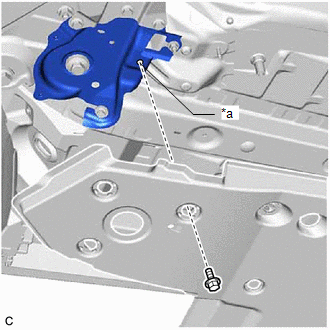
| *a | Bolt Hole |
Torque:
7.5 N·m {76 kgf·cm, 66 in·lbf}
(a) Type A:
| (1) Install the front floor cover RH with the grommet (B) and 6 clips (C). |
|
.png)
(2) Install the 3 bolts and 4 clips (A).
Torque:
Bolt :
7.5 N·m {76 kgf·cm, 66 in·lbf}
(b) Type B:
| (1) Install the front floor cover RH with the grommet (B) and 6 clips (C). |
|
.png)
(2) Install the 4 bolts and 4 clips (A).
Torque:
Bolt :
7.5 N·m {76 kgf·cm, 66 in·lbf}
11. INSTALL TAIL EXHAUST PIPE ASSEMBLY
(a) Install a new gasket to the center exhaust pipe assembly.
(b) Connect the tail exhaust pipe assembly to the 2 exhaust pipe supports.
(c) Install the tail exhaust pipe assembly to the center exhaust pipe assembly with 2 new bolts.
Torque:
43 N·m {438 kgf·cm, 32 ft·lbf}
12. INSTALL TAIL EXHAUST PIPE ASSEMBLY LH
(a) Install a new gasket to the center exhaust pipe assembly.
(b) Connect the tail exhaust pipe assembly LH to the 2 exhaust pipe supports.
(c) Install the tail exhaust pipe assembly LH to the center exhaust pipe assembly with 2 new bolts.
Torque:
43 N·m {438 kgf·cm, 32 ft·lbf}
13. INSPECT FOR EXHAUST GAS LEAK
If gas is leaking, tighten the areas necessary to stop the leak. Replace damaged parts as necessary.
(a) Perform "Inspection After Repair" after repairing an exhaust gas leak.
Click here
READ NEXT:
 Intake Air Control Valve(for Acis)
On-vehicle InspectionON-VEHICLE INSPECTION PROCEDURE 1. INSPECT INTAKE AIR CONTROL VALVE (for ACIS) (a) Disconnect the vacuum hose sub-assembly from the intake air control valve (for ACIS).
Components
COMPONENTS ILLUSTRATION *1 FRONT CENTER UPPER SUSPENSION BRACE SUB-ASSEMBLY - - Tightening torque for "Major areas involving basic vehicle performance such as moving/turning/stopping"
SEE MORE:
Data List / Active Test
DATA LIST / ACTIVE TEST DATA LIST NOTICE: In the table below, the values listed under "Normal Condition" are reference values. Do not depend solely on these reference values when deciding whether a part is faulty or not. (a) Connect the Techstream to the DLC3. (b) Turn the power switch on (IG). (c)
Drive Motor Inverter Temperature Sensor "A" Circuit Short to Ground (P0AED11,P0AED15)
DESCRIPTION The motor generator control ECU (MG ECU), which is built into in the inverter with converter assembly, detects the temperature of the motor inverter using the motor inverter temperature sensor. The inverter cooling system operates independently of the engine cooling system. The motor gen
