Lexus ES: Components
COMPONENTS
ILLUSTRATION
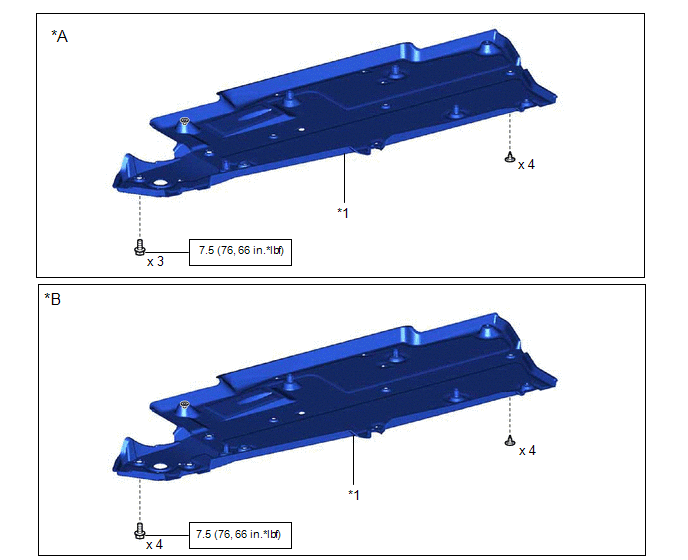
| *A | Type A | *B | Type B |
| *1 | FRONT FLOOR COVER RH | - | - |
.png) | N*m (kgf*cm, ft.*lbf): Specified torque | - | - |
ILLUSTRATION
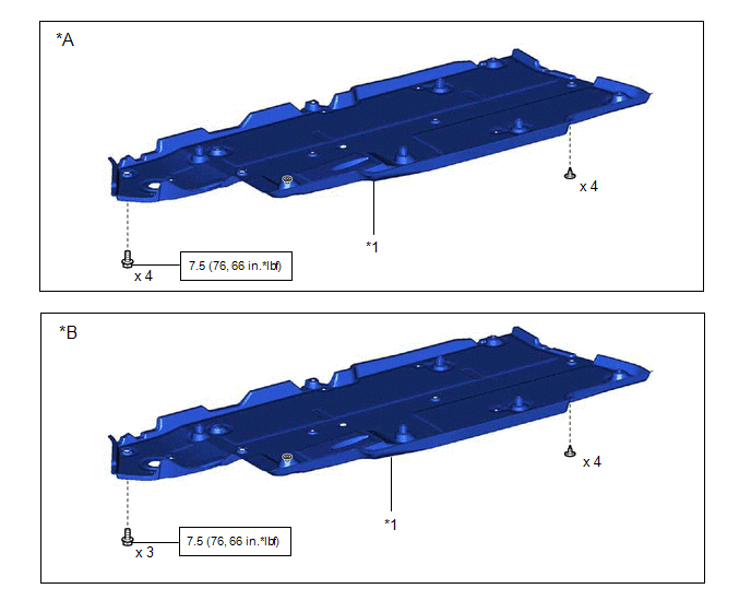
| *A | Type A | *B | Type B |
| *1 | FRONT FLOOR COVER LH | - | - |
| | N*m (kgf*cm, ft.*lbf): Specified torque | - | - |
ILLUSTRATION
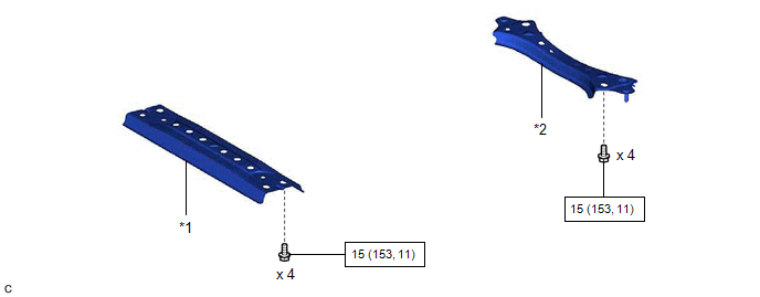
| *1 | CENTER FLOOR CROSSMEMBER BRACE | *2 | FRONT CENTER FLOOR BRACE |
| | N*m (kgf*cm, ft.*lbf): Specified torque | - | - |
ILLUSTRATION
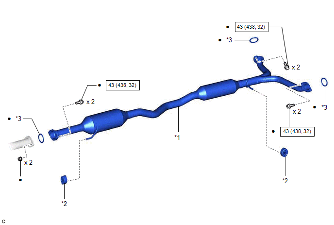
| *1 | CENTER EXHAUST PIPE ASSEMBLY | *2 | EXHAUST PIPE SUPPORT |
| *3 | GASKET | - | - |
| | N*m (kgf*cm, ft.*lbf): Specified torque | ● | Non-reusable part |
ILLUSTRATION
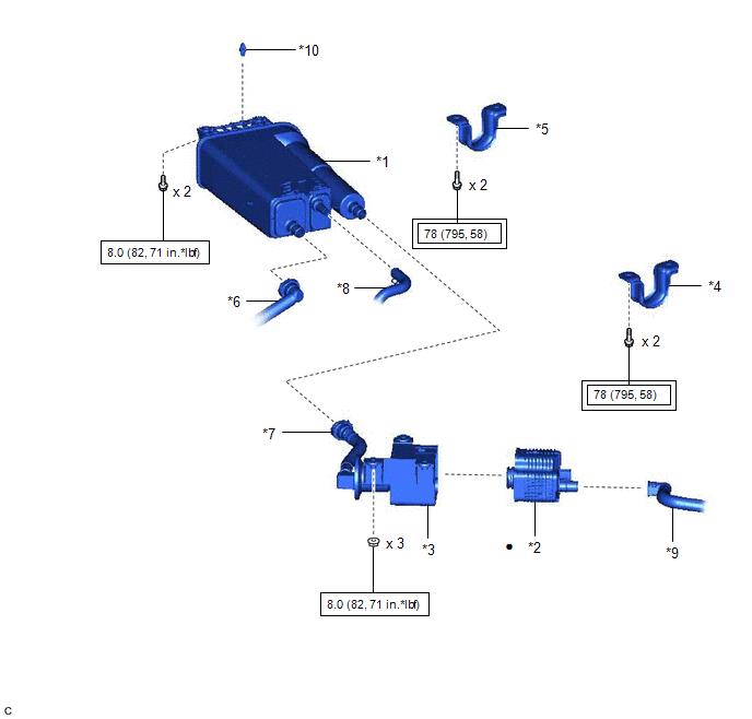
| *1 | CANISTER (CHARCOAL CANISTER ASSEMBLY) | *2 | LEAK DETECTION PUMP SUB-ASSEMBLY |
| *3 | NO. 2 CHARCOAL CANISTER SUB-ASSEMBLY | *4 | REAR NO. 1 STABILIZER BAR BRACKET LH |
| *5 | REAR NO. 1 STABILIZER BAR BRACKET RH | *6 | FUEL TANK VENT HOSE |
| *7 | VENT LINE HOSE | *8 | PURGE LINE HOSE |
| *9 | AIR LINE TUBE | *10 | CLIP |
 | Tightening torque for "Major areas involving basic vehicle performance such as moving/turning/stopping": N*m (kgf*cm, ft.*lbf) | | N*m (kgf*cm, ft.*lbf): Specified torque |
| ● | Non-reusable part | - | - |
READ NEXT:
 Removal
REMOVAL CAUTION / NOTICE / HINT The necessary procedures (adjustment, calibration, initialization or registration) that must be performed after parts are removed and installed, or replaced during cani
Inspection
INSPECTION PROCEDURE 1. INSPECT CANISTER (CHARCOAL CANISTER ASSEMBLY) (a) Visually check the canister (charcoal canister assembly). (1) Visually check the canister (charcoal canister assembly) for
Installation
INSTALLATION PROCEDURE 1. INSTALL LEAK DETECTION PUMP SUB-ASSEMBLY HINT: Only perform this procedure when replacement of the leak detection pump sub-assembly is necessary. (a) Engage the 2 claws to
SEE MORE:
RR Speed Sensor Wrong Installation (X0454)
DESCRIPTION Code Tester Display Measurement Item Trouble Area X0454 RR Speed Sensor Wrong Installation History of rear speed sensor RH being installed incorrectly Rear Speed Sensor RH PROCEDURE 1. CHECK FOR DTCs (HEALTH CHECK) (a) Perform the Health Check using the Tec
System Description
SYSTEM DESCRIPTION DISC PLAYER OUTLINE (a) A disc player uses a laser pickup to read digital signals recorded on a disc. By converting the digital signals to analog, it can play music and audio. CAUTION: Do not look directly at the laser pickup because the disc player uses an invisible laser beam. B
