Lexus ES: Inspection
INSPECTION
PROCEDURE
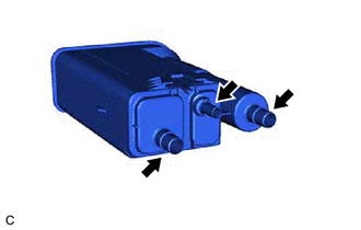
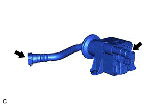
1. INSPECT CANISTER (CHARCOAL CANISTER ASSEMBLY)
| (a) Visually check the canister (charcoal canister assembly). (1) Visually check the canister (charcoal canister assembly) for cracks or damage. If cracks or damage are found, replace the canister (charcoal canister assembly). |
|
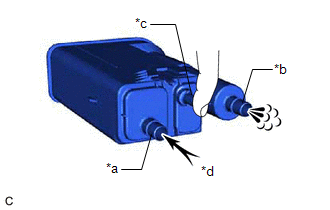
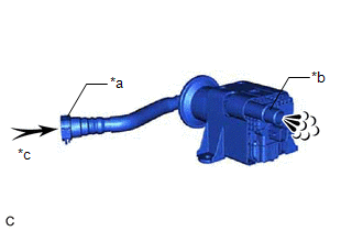
(b) Check canister (charcoal canister assembly) operation.
| (1) With the purge line port closed, blow 0.5 kPa (0.005 kgf/cm2, 0.1 psi) of air into the vent line port, and check that air flows from the air line port. If the result is not as specified, replace the canister (charcoal canister assembly). |
|
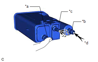
| (2) With the vent line port closed, blow 0.5 kPa (0.005 kgf/cm2, 0.1 psi) of air into the air line port, and check that air flows from the purge line port. If the result is not as specified, replace the canister (charcoal canister assembly). |
|
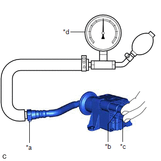
(c) Check for air leaks.
| (1) Connect a pressure gauge to the vent line port. |
|
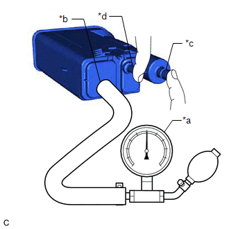
(2) With the purge line port and air line port closed, apply 20 kPa (150 mmHg, 5.91 in. Hg) of pressurized air into the vent line port, then confirm that pressure is maintained for 1 minute.
If the result is not as specified, replace the canister (charcoal canister assembly).
2. INSPECT NO. 2 CHARCOAL CANISTER SUB-ASSEMBLY
| (a) Visually check the No. 2 charcoal canister sub-assembly. (1) Visually check the No. 2 charcoal canister sub-assembly for cracks or damage. If cracks or damage are found, replace the No. 2 charcoal canister sub-assembly. |
|
(b) Check No. 2 charcoal canister sub-assembly operation.
| (1) Blow 0.5 kPa (0.005 kgf/cm2, 0.1 psi) of air into the port A, and check that air flows from the port B. If the result is not as specified, replace the No. 2 charcoal canister sub-assembly. |
|
(c) Check for air leaks.
| (1) Connect a pressure gauge to the port A. |
|
(2) With the port B and leak detection pump sub-assembly connector closed, apply 20 kPa (150 mmHg, 5.91 in. Hg) of pressurized air into the port A, then confirm that pressure is maintained for 1 minute.
If the result is not as specified, replace the No. 2 charcoal canister sub-assembly.
(d) Check the leak detection pump sub-assembly.
| (1) Connect a positive (+) lead from the battery to terminal 5 and a negative (-) lead to terminal 1. |
|
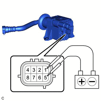
(2) Check that a clicking sound is heard from the leak detection pump sub-assembly.
If the result is not as specified, replace the leak detection pump sub-assembly.
READ NEXT:
 Installation
INSTALLATION PROCEDURE 1. INSTALL LEAK DETECTION PUMP SUB-ASSEMBLY HINT: Only perform this procedure when replacement of the leak detection pump sub-assembly is necessary. (a) Engage the 2 claws to
Parts Location
PARTS LOCATION ILLUSTRATION *1 CANISTER (CHARCOAL CANISTER ASSEMBLY) *2 FUEL TANK CAP ASSEMBLY *3 PCV VALVE (VENTILATION VALVE SUB-ASSEMBLY) *4 PURGE VALVE (PURGE VSV) *5 ECM
SEE MORE:
High Temperature Adjustment
HIGH TEMPERATURE ADJUSTMENT CAUTION / NOTICE / HINT The necessary procedures (adjustment, calibration, initialization or registration) that must be performed after parts are removed and installed, or replaced during automatic transaxle fluid replacement are shown below. Necessary Procedures After Pa
"E" Camshaft Position Actuator Bank 1 Signal Invalid (P136629)
DESCRIPTION Refer to DTC P001001. Click here DTC No. Detection Item DTC Detection Condition Trouble Area MIL Memory Note P136629 "E" Camshaft Position Actuator Bank 1 Signal Invalid Malfunction in diagnostic signal (VTM) of cam timing control motor with EDU assembly is detec
