Lexus ES: Components
COMPONENTS
ILLUSTRATION
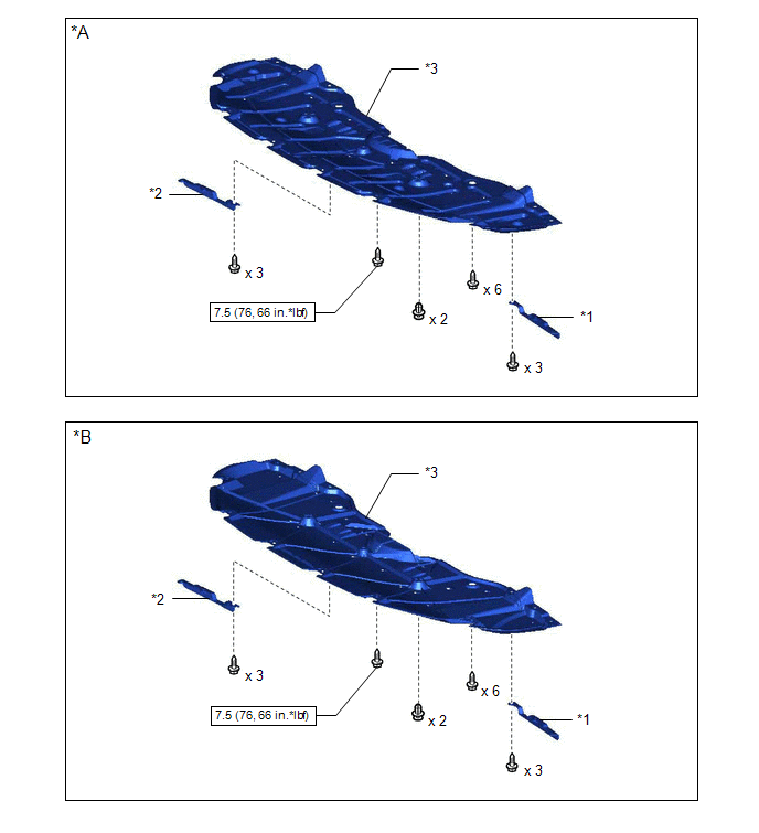
| *A | Type A | *B | Type B |
| *1 | FRONT WHEEL OPENING EXTENSION PAD LH | *2 | FRONT WHEEL OPENING EXTENSION PAD RH |
| *3 | NO. 1 ENGINE UNDER COVER | - | - |
 | N*m (kgf*cm, ft.*lbf): Specified torque | - | - |
ILLUSTRATION
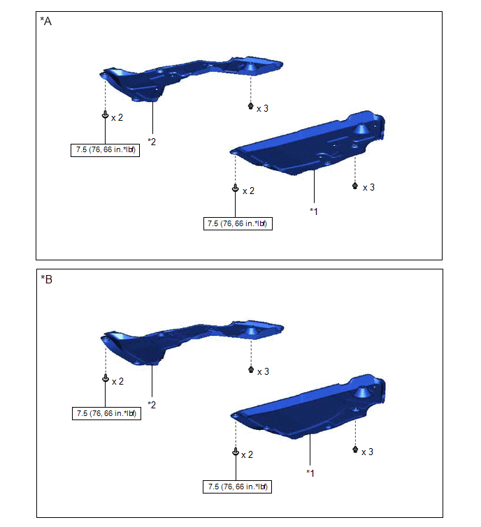
| *A | Type A | *B | Type B |
| *1 | NO. 3 ENGINE UNDER COVER | *2 | NO. 2 ENGINE UNDER COVER |
| | N*m (kgf*cm, ft.*lbf): Specified torque | - | - |
ILLUSTRATION
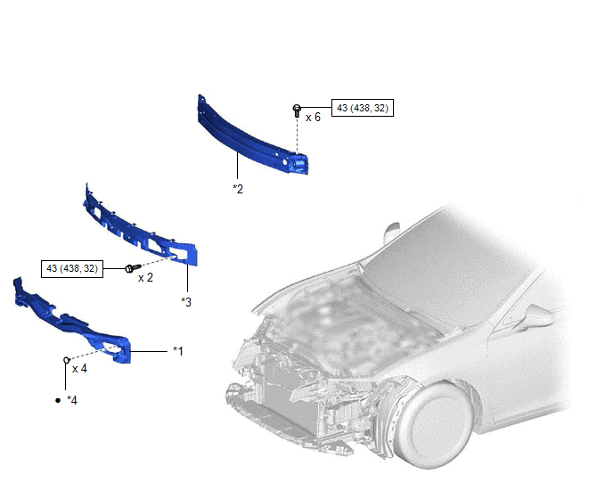
| *1 | FRONT BUMPER ENERGY ABSORBER | *2 | FRONT BUMPER REINFORCEMENT SUB-ASSEMBLY |
| *3 | NO. 2 FRONT BUMPER MOUNTING BRACKET | *4 | CLIP |
| | N*m (kgf*cm, ft.*lbf): Specified torque | ● | Non-reusable part |
ILLUSTRATION
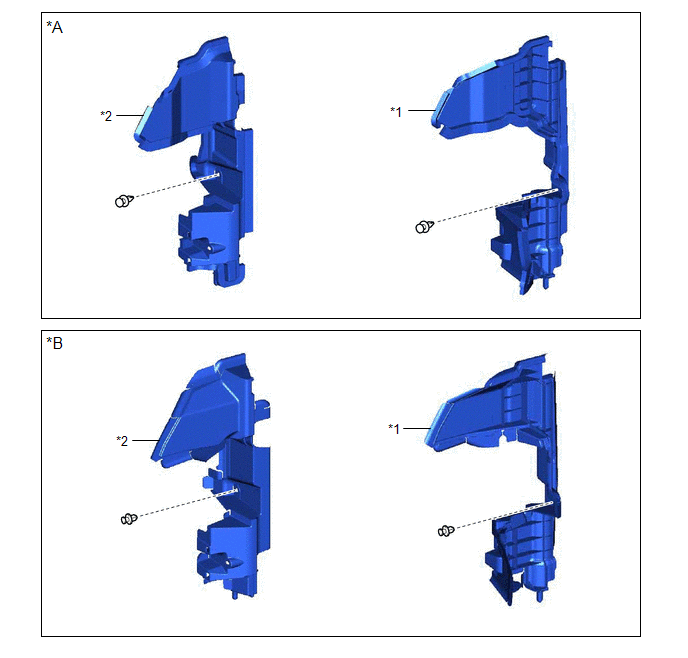
| *A | Type A | *B | Type B |
| *1 | NO. 1 RADIATOR AIR GUIDE LH | *2 | NO. 1 RADIATOR AIR GUIDE RH |
ILLUSTRATION
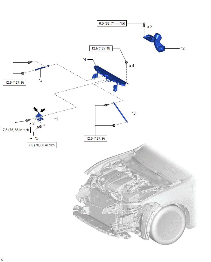
| *1 | HOOD LOCK ASSEMBLY | *2 | INLET AIR CLEANER ASSEMBLY |
| *3 | UPPER RADIATOR MOUNTING BRACKET | *4 | UPPER RADIATOR SUPPORT SUB-ASSEMBLY |
| *5 | HOOD LOCK NUT CAP | - | - |
| | N*m (kgf*cm, ft.*lbf): Specified torque | ● | Non-reusable part |
 | MP grease | - | - |
ILLUSTRATION
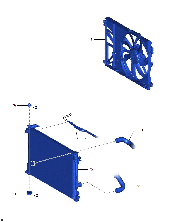
| *1 | LOWER RADIATOR SUPPORT | *2 | NO. 1 RADIATOR HOSE |
| *3 | NO. 2 RADIATOR HOSE | *4 | NO. 5 WATER BY-PASS HOSE |
| *5 | RADIATOR ASSEMBLY | *6 | RADIATOR SUPPORT CUSHION |
| *7 | FAN WITH MOTOR ASSEMBLY | - | - |
READ NEXT:
 On-vehicle Inspection
ON-VEHICLE INSPECTION CAUTION / NOTICE / HINT CAUTION: Do not remove the radiator cap sub-assembly while the engine and radiator assembly are still hot. Pressurized, hot engine coolant and steam may b
Removal
REMOVAL CAUTION / NOTICE / HINT The necessary procedures (adjustment, calibration, initialization, or registration) that must be performed after parts are removed and installed, or replaced during rad
Installation
INSTALLATION PROCEDURE 1. INSTALL LOWER RADIATOR SUPPORT (a) Install the 2 lower radiator supports to the radiator assembly. 2. INSTALL RADIATOR SUPPORT CUSHION (a) Install the 2 radiator support cush
SEE MORE:
Steering Angle Initialization Incomplete (C1694)
DESCRIPTION This DTC is stored when the rear television camera assembly judges that the maximum steering angle has not been memorized (steering angle setting is incomplete). DTC No. Detection Item DTC Detection Condition Trouble Area C1694 Steering Angle Initialization Incomplete Ma
Components
COMPONENTS ILLUSTRATION *A w/ Dust Cap - - *1 FUEL PRESSURE SENSOR (FUEL DELIVERY PIPE WITH SENSOR ASSEMBLY LH) *2 FUEL PIPE PLUG SUB-ASSEMBLY *3 DUST CAP SUB-ASSEMBLY *4 O-RING *5 NO. 1 FUEL INJECTOR BACK-UP RING *6 NO. 2 FUEL INJECTOR BACK-UP RING *7 N
