Lexus ES: Removal
REMOVAL
CAUTION / NOTICE / HINT
The necessary procedures (adjustment, calibration, initialization, or registration) that must be performed after parts are removed and installed, or replaced during radiator assembly removal/installation are shown below.
Necessary Procedure After Parts Removed/Installed/Replaced| Replaced Part or Performed Procedure | Necessary Procedure | Effect/Inoperative Function when Necessary Procedure not Performed | Link |
|---|---|---|---|
| Front bumper assembly | Front television camera view adjustment | Panoramic View Monitor System | for Initialization for Calibration |
|
| | |
| Headlight ECU sub-assembly LH |
| Lighting System | |
PROCEDURE
1. REMOVE FRONT WHEEL OPENING EXTENSION PAD LH
Click here .gif)
2. REMOVE FRONT WHEEL OPENING EXTENSION PAD RH
Click here
3. REMOVE NO. 1 ENGINE UNDER COVER
Click here
4. REMOVE NO. 3 ENGINE UNDER COVER
Click here
5. REMOVE NO. 2 ENGINE UNDER COVER
Click here
6. DRAIN ENGINE COOLANT
Click here
7. REMOVE HEADLIGHT ASSEMBLY
for LED Type Turn Signal Light: Click here
for Bulb Type Turn Signal Light: Click here
8. REMOVE THERMISTOR ASSEMBLY
Click here
9. REMOVE FRONT BUMPER ENERGY ABSORBER
Click here
10. REMOVE NO. 2 FRONT BUMPER MOUNTING BRACKET
Click here
11. REMOVE FRONT BUMPER REINFORCEMENT SUB-ASSEMBLY
Click here
12. REMOVE HOOD LOCK ASSEMBLY
Click here
13. REMOVE INLET AIR CLEANER ASSEMBLY
Click here
14. REMOVE UPPER RADIATOR MOUNTING BRACKET
| (a) Disconnect the 2 horn connectors. |
|
| (b) Remove the 2 bolts, 2 nuts and 2 upper radiator mounting brackets. |
|
15. REMOVE NO. 1 RADIATOR AIR GUIDE LH
| (a) Remove the clip and disengage the claw. |
|
(b) Disengage the guide to remove the No. 1 radiator air guide LH with the front radiator side air guide plate LH.
16. REMOVE NO. 1 RADIATOR AIR GUIDE RH
| (a) Remove the clip and disengage the claw. |
|

(b) Disengage the guide to remove the No. 1 radiator air guide RH.
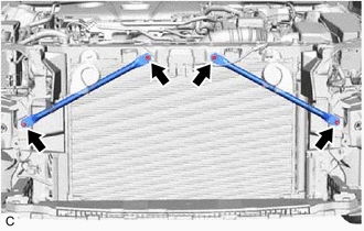
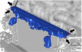
17. REMOVE UPPER RADIATOR SUPPORT SUB-ASSEMBLY
| (a) Disengage the clamp to disconnect the hood lock control cable assembly from the upper radiator support sub-assembly. |
|
| (b) Disengage the 4 clamps to disconnect the wire harness from the upper radiator support sub-assembly. |
|
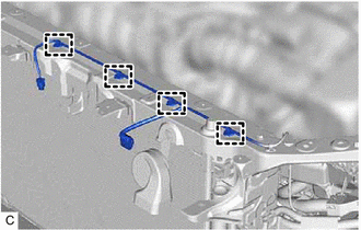
| (c) Remove the 4 bolts and upper radiator support sub-assembly. |
|
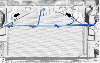
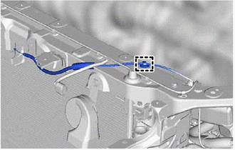
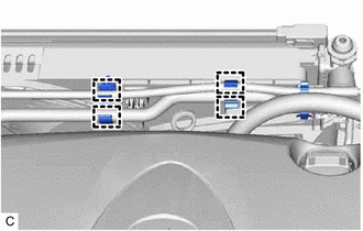
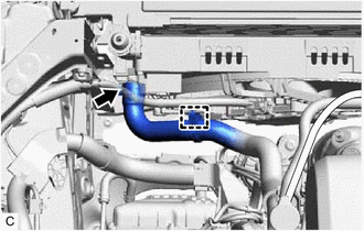
18. DISCONNECT NO. 5 WATER BY-PASS HOSE
| (a) Disengage the 4 clamps to disconnect the No. 5 water by-pass hose and No. 6 water by-pass hose from the hose clamp. |
|
| (b) Slide the clip and disconnect the No. 5 water by-pass hose from the radiator assembly. |
|
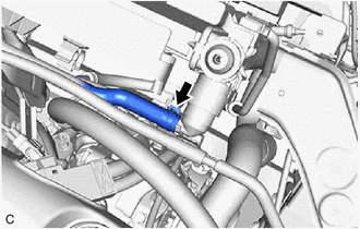
19. DISCONNECT NO. 1 RADIATOR HOSE
| (a) Disengage the clamp and disconnect the No. 1 radiator hose from the fan with motor assembly. |
|
(b) Slide the clip and disconnect the No. 1 radiator hose from the radiator assembly.
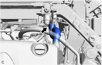
20. DISCONNECT NO. 2 RADIATOR HOSE
| (a) Slide the clip and disconnect the No. 2 radiator hose from the radiator assembly. |
|
21. REMOVE RADIATOR ASSEMBLY
| (a) Disengage the 2 claws. |
|
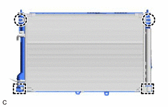
(b) Disengage the 2 guides to separate the cooler condenser assembly from the radiator assembly.
NOTICE:
Make sure not to damage the cooler condenser assembly when separating the cooler condenser assembly.
(c) Disconnect the cooling fan motor connector.
| (1) Disengage the claw and raise the lock lever to disconnect the cooling fan motor connector as shown in the illustration. NOTICE: After disconnecting the cooling fan motor connector, make sure that dirt, water or other foreign matter does not contact the connecting parts of the cooling fan motor connector. |
|
.png)
(2) Disengage the wire harness clamp.
(d) Remove the radiator assembly with the fan with motor assembly from the vehicle body.
NOTICE:
Do not apply excessive force to the cooler condenser assembly or pipe when removing the radiator assembly with the fan with motor assembly.
| (e) Disengage the 2 claws. |
|
.png)
(f) Disengage the 2 guides to remove the fan with motor assembly from the radiator assembly.
NOTICE:
Do not damage the radiator assembly when removing the fan with motor assembly.
22. REMOVE RADIATOR SUPPORT CUSHION
(a) Remove the 2 radiator support cushions from the radiator assembly.
23. REMOVE LOWER RADIATOR SUPPORT
(a) Remove the 2 lower radiator supports from the radiator assembly.
READ NEXT:
 Installation
INSTALLATION PROCEDURE 1. INSTALL LOWER RADIATOR SUPPORT (a) Install the 2 lower radiator supports to the radiator assembly. 2. INSTALL RADIATOR SUPPORT CUSHION (a) Install the 2 radiator support cush
Components
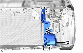
COMPONENTS ILLUSTRATION *1 ENGINE WIRE *2 FRONT NO. 1 ENGINE MOUNTING BRACKET LH *3 WATER INLET WITH THERMOSTAT SUB-ASSEMBLY *4 GASKET *5 WATER BY-PASS HOSE *6 WIRE HARNE
SEE MORE:
PBD/PTL Closer Switch (B2251)
DESCRIPTION DTC B2251 is output if there is a malfunction in the half latch switch circuit of the luggage door closer assembly. DTC No. Detection Item DTC Detection Condition Trouble Area B2251 PBD/PTL Closer Switch When luggage door is opening or closing, malfunction occurs in half
Hybrid/EV Battery "A" Voltage Sensor/Boosting Converter Voltage Sensor "A" Signal Compare Failure (P1C2D62)
DTC SUMMARY MALFUNCTION DESCRIPTION The hybrid vehicle control ECU detects a VB sensor or VL sensor malfunction. The cause of this malfunction may be one of the following: Inverter voltage (VB or VL) sensor internal circuit malfunction
Voltage sensor malfunction
Motor generator control ECU (MG
