Lexus ES: Components
COMPONENTS
ILLUSTRATION
.png)
| *1 | FRONT CENTER UPPER SUSPENSION BRACE SUB-ASSEMBLY | - | - |
.png) | Tightening torque for "Major areas involving basic vehicle performance such as moving/turning/stopping": N*m (kgf*cm, ft.*lbf) | .png) | N*m (kgf*cm, ft.*lbf): Specified torque |
| *T1 | Bolt color black: 8.0 N*m (82 kgf*cm, 71 in.*lbf) Bolt color silver: 8.9 N*m (91 kgf*cm, 79 in.*lbf) | - | - |
ILLUSTRATION
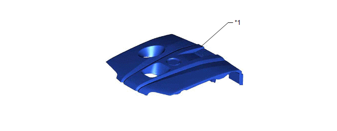
| *1 | NO. 1 ENGINE COVER SUB-ASSEMBLY | - | - |
ILLUSTRATION
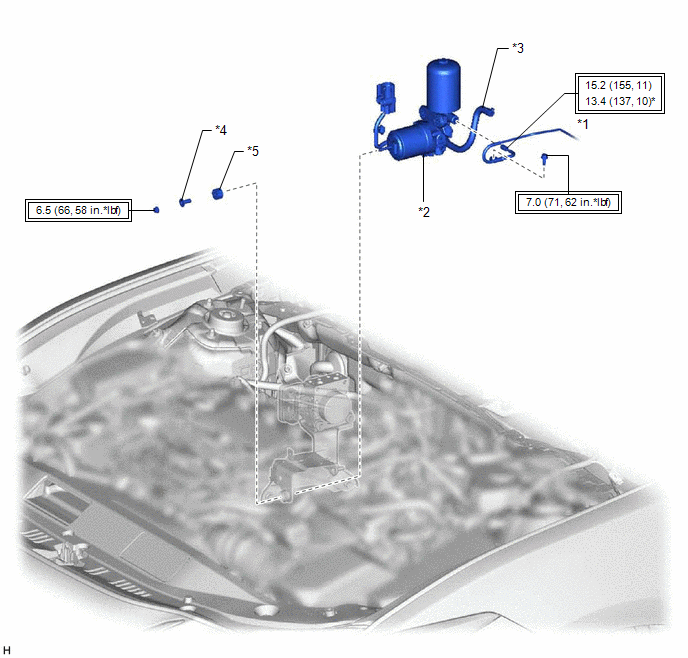
| *1 | ACCUMULATOR TO BRAKE MASTER CYLINDER TUBE | *2 | BRAKE BOOSTER PUMP ASSEMBLY |
| *3 | NO. 2 BRAKE ACTUATOR HOSE | *4 | BRAKE ACTUATOR CASE COLLAR |
| *5 | BRAKE BOOSTER PUMP BUSHING | - | - |
| | Tightening torque for "Major areas involving basic vehicle performance such as moving/turning/stopping": N*m (kgf*cm, ft.*lbf) | * | For use with a union nut wrench |
ILLUSTRATION
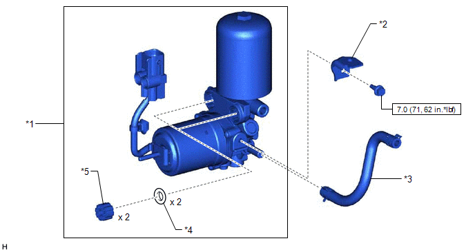
| *1 | BRAKE BOOSTER PUMP ASSEMBLY | *2 | NO. 1 BRAKE TUBE CLAMP BRACKET |
| *3 | NO. 2 BRAKE ACTUATOR HOSE | *4 | BRAKE BOOSTER PUMP COLLAR |
| *5 | BRAKE BOOSTER PUMP BUSHING | - | - |
| | N*m (kgf*cm, ft.*lbf): Specified torque | - | - |
READ NEXT:
 Disposal
DISPOSAL PROCEDURE 1. DISPOSE OF BRAKE BOOSTER PUMP ASSEMBLY (a) Remove the accumulator from the brake booster pump assembly. (b) Secure the accumulator in a vise. (c) Using a hacksaw, make a cut in t
Inspection
INSPECTION PROCEDURE 1. INSPECT BRAKE BOOSTER PUMP ASSEMBLY (a) Measure the resistance according to the value(s) in the table below. Standard Resistance: Tester Connection Condition Specifi
Installation
INSTALLATION PROCEDURE 1. INSTALL NO. 1 BRAKE TUBE CLAMP BRACKET (a) Install the No. 1 brake tube clamp bracket to the brake booster pump assembly with the bolt. Torque: 7.0 N·m {71 kgf·cm, 62 in·
SEE MORE:
On-vehicle Inspection
ON-VEHICLE INSPECTION PROCEDURE 1. INSPECT PARKING BRAKE ACTUATOR ASSEMBLY (for Gasoline Model) HINT: Using the GTS to perform the Utilities allows relays, VSVs and actuators and other items to be operated without removing any parts. This non-intrusive functional inspection can be very useful becaus
Emergency Call Switch Circuit Short to Ground (B15C511,B15C513)
DESCRIPTION If the DCM (telematics transceiver) detects an error in the communication between the DCM (telematics transceiver) and the map light sub-assembly (manual (SOS) switch) as a result of the DCM (telematics transceiver) self check, this DTC will be stored. DTC No. Detection Item DTC D
