Lexus ES: Disposal
DISPOSAL
PROCEDURE
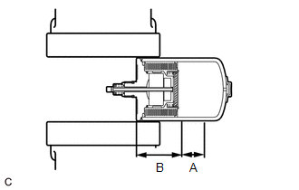
1. DISPOSE OF BRAKE BOOSTER PUMP ASSEMBLY
(a) Remove the accumulator from the brake booster pump assembly.
(b) Secure the accumulator in a vise.
(c) Using a hacksaw, make a cut in the side of the accumulator within location (A) to release the high-pressure gas.
| Location | Length |
|---|---|
| A | 25 mm (0.984 in.) |
| B | 60 mm (2.36 in.) |
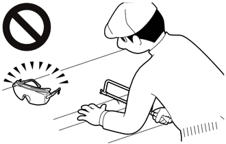
- Wear protective glasses.
- Small pieces of metal may fly out when cutting into the accumulator. Put a cloth over the hacksaw when cutting the accumulator. Cut the accumulator slowly so that the gas will be released gradually.
HINT:
Nitrogen gas, which is colorless, odorless and harmless, will be discharged.
READ NEXT:
 Inspection
INSPECTION PROCEDURE 1. INSPECT BRAKE BOOSTER PUMP ASSEMBLY (a) Measure the resistance according to the value(s) in the table below. Standard Resistance: Tester Connection Condition Specifi
Installation
INSTALLATION PROCEDURE 1. INSTALL NO. 1 BRAKE TUBE CLAMP BRACKET (a) Install the No. 1 brake tube clamp bracket to the brake booster pump assembly with the bolt. Torque: 7.0 N·m {71 kgf·cm, 62 in·
Removal
REMOVAL CAUTION / NOTICE / HINT The necessary procedures (adjustment, calibration, initialization, or registration) that must be performed after parts are removed, installed, or replaced during brake
SEE MORE:
DC/DC Converter Current Sensor Signal Bias Level Out of Range / Zero Adjustment Failure (P0E5128)
DTC SUMMARY MALFUNCTION DESCRIPTION This DTC is stored when an abnormal current sensor output signal is detected. The cause of this malfunction may be one of the following: Internal inverter malfunction
Current sensor malfunction
Inverter with converter assembly internal circuit malfunction
Components
COMPONENTS ILLUSTRATION *A w/o AVS - - *1 FRONT SHOCK ABSORBER WITH COIL SPRING *2 FRONT SPEED SENSOR *3 FRONT STABILIZER LINK ASSEMBLY *4 FRONT FLEXIBLE HOSE *5 STEERING KNUCKLE *6 FRONT SHOCK ABSORBER LOCK NUT CAP Tightening torque for "Major areas in
© 2016-2026 Copyright www.lexguide.net
