Lexus ES: Components
COMPONENTS
ILLUSTRATION
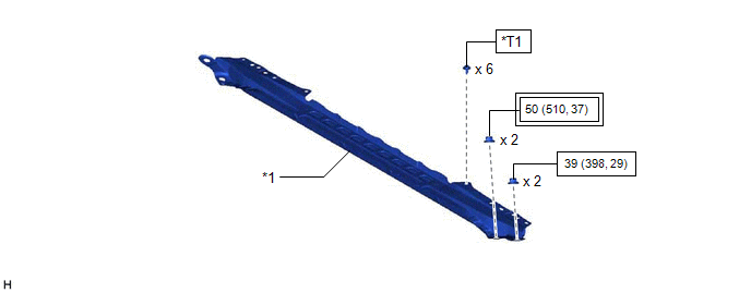
| *1 | FRONT CENTER UPPER SUSPENSION BRACE SUB-ASSEMBLY | - | - |
.png) | Tightening torque for "Major areas involving basic vehicle performance such as moving/turning/stopping": N*m (kgf*cm, ft.*lbf) |  | N*m (kgf*cm, ft.*lbf): Specified torque |
| *T1 | Bolt color black: 8.0 N*m (82 kgf*cm, 71 in.*lbf) Bolt color silver: 8.9 N*m (91 kgf*cm, 79 in.*lbf) | - | - |
ILLUSTRATION
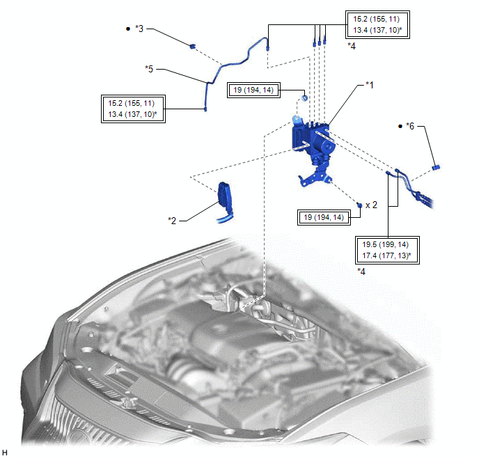
| *1 | BRAKE ACTUATOR WITH BRACKET | *2 | CONNECTOR |
| *3 | BRAKE TUBE CLAMP | *4 | BRAKE LINE |
| *5 | FRONT NO. 3 BRAKE TUBE | *6 | NO. 4 BRAKE TUBE CLAMP |
| | Tightening torque for "Major areas involving basic vehicle performance such as moving/turning/stopping": N*m (kgf*cm, ft.*lbf) | * | For use with a union nut wrench |
| ● | Non-reusable part | - | - |
ILLUSTRATION
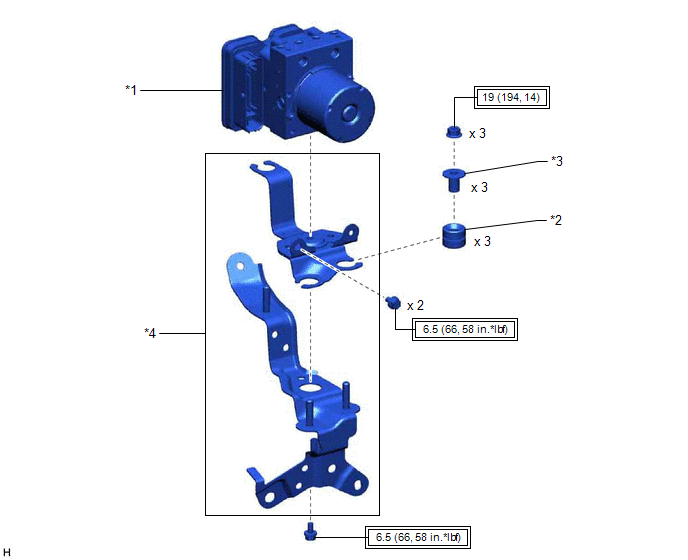
| *1 | BRAKE ACTUATOR ASSEMBLY | *2 | BRAKE ACTUATOR BRACKET CUSHION |
| *3 | NO. 2 BRAKE ACTUATOR CASE COLLAR | *4 | BRAKE ACTUATOR BRACKET ASSEMBLY |
| | Tightening torque for "Major areas involving basic vehicle performance such as moving/turning/stopping": N*m (kgf*cm, ft.*lbf) | - | - |
READ NEXT:
 Installation
INSTALLATION CAUTION / NOTICE / HINT HINT: The parking brake indicator light blinks (red) when the engine switch is turned on (IG) after replacing the brake actuator assembly. Operate the electric par
On-vehicle Inspection
ON-VEHICLE INSPECTION PROCEDURE 1. CONNECT TECHSTREAM (a) Connect the Techstream to the DLC3 with the ignition switch off. (b) Start the engine and run it at idle. (c) Turn the Techstream on. (d) Ente
Removal
REMOVAL CAUTION / NOTICE / HINT The necessary procedures (adjustment, calibration, initialization or registration) that must be performed after parts are removed and installed, or replaced during brak
SEE MORE:
How To Proceed With Troubleshooting
CAUTION / NOTICE / HINT HINT:
Use the following procedure to troubleshoot the windshield deicer system.
*: Use the Techstream.
PROCEDURE 1. VEHICLE BROUGHT TO WORKSHOP
NEXT 2. CUSTOMER PROBLEM ANALYSIS HINT:
In troubleshooting, confirm that the problem s
System Diagram
SYSTEM DIAGRAM Communication Table Sender Receiver Signal Line Main Body ECU (Multiplex Network Body ECU) Sliding Roof ECU (Sliding Roof Drive Gear Assembly)
Sliding roof operation permission signal
IG signal
Front door courtesy light switch assembly signal
Vehicle speed
