Lexus ES: Cold Start Ignition Timing Performance (P050B00)
MONITOR DESCRIPTION
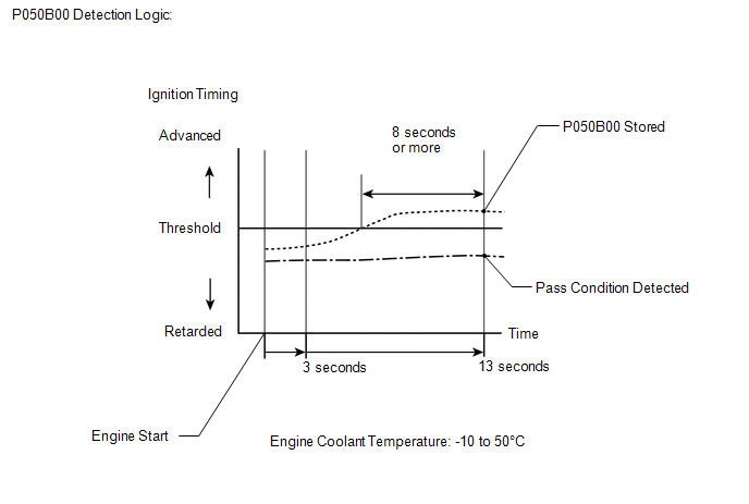
This monitor will run when the engine is started at an engine coolant temperature of -10 to 50°C (14 to 122°F). The DTC is stored after the engine idles for 13 seconds (2 trip detection logic).
The DTC is designed to monitor the ignition timing at cold start. When the engine is started at an engine coolant temperature of less than 50°C (122°F), the ECM checks the ignition timing during engine idling. If the ignition timing advances beyond the specified level within 10 seconds, the ECM interprets this as a malfunction. The MIL is illuminated and a DTC is stored when the malfunction is detected in consecutive driving cycles (2 trip detection logic).
NOTICE:
The idle speed control learned values are cleared by performing a learned value reset. Idle speed control learning needs to be performed before this DTC can be stored.
HINT:
Idle speed control learning is performed when the engine is warmed up and has been idling for 5 minutes.
| DTC No. | Detection Item | DTC Detection Condition | Trouble Area | MIL | Memory | Note |
|---|---|---|---|---|---|---|
| P050B00 | Cold Start Ignition Timing Performance | Insufficient ignition timing retard at cold start (2 trip detection logic). |
| Comes on | DTC stored | SAE Code: P050B |
MONITOR STRATEGY
| Related DTCs | P050B: Cold start ignition timing performance |
| Required Sensors/Components (Main) | Throttle body with motor assembly |
| Required Sensors/Components (Related) | Mass air flow meter sub-assembly Engine coolant temperature sensor |
| Frequency of Operation | Once per driving cycle |
| Duration | 10 seconds |
| MIL Operation | 2 driving cycles |
| Sequence of Operation | None |
TYPICAL ENABLING CONDITIONS
| Monitor runs whenever the following DTCs are not stored | P0010, P0020 (VVT oil control solenoid bank 1, 2) P0011, P0021 (VVT system bank 1, 2 - advance) P0012, P0022 (VVT system bank 1, 2 - retard) P0013, P0023 (Exhaust VVT oil control solenoid bank 1, 2) P0014, P0024 (Exhaust VVT system bank 1, 2 - advance) P0015, P0025 (Exhaust VVT system bank 1, 2 - retard) P0016, P0018 (VVT system bank 1, 2 - misalignment) P0017, P0019 (Exhaust VVT system bank 1, 2 - misalignment) P0087, P0088, P0191, P0192, P0193 (Fuel pressure sensor (for high pressure side)) P0101, P0102, P0103 (Mass air flow meter) P0116, P0117, P0118 (Engine coolant temperature sensor) P011B (Engine coolant temperature/intake air temperature sensor correlation) P0121, P0122, P0123, P0222, P0223, P2135 (Throttle position sensor) P0125 (Insufficient coolant temperature for closed loop fuel control) P014C, P014D, P014E, P014F, P015A, P015B, P015C, P015D, P2195, P2196, P2197, P2198, P2237, P2238, P2239, P2240, P2241, P2242, P2252, P2253, P2255, P2256 (Air fuel ratio sensor) P0171, P0172, P0174, P0175 (Fuel system) P0201, P0202, P0203, P0204, P0205, P0206, P062D, P21CF, P21D0, P21D1, P21D2, P21D3, P21D4 (Fuel injector) P0300 - P0306 (Misfire) P0335, P0337, P0338 (Crankshaft position sensor) P0340, P0342, P0343, P0345, P0347, P0348 (Camshaft position sensor) P0351 - P0356 (Igniter) P0365, P0367, P0368, P0390, P0392, P0393 (Exhaust camshaft position sensor) P0500 (Vehicle speed sensor) P0657, P2102, P2103, P2111, P2112, P2119 (Throttle actuator) P0705 (Shift lever position switch) P107B, P107C, P107D (Fuel pressure sensor (for low pressure side)) P11EA, P11EB, P11EC, P11ED, P11EE, P11EF, P11F0, P11F1, P219A, P219B, P219C, P219D, P219E, P219F, P21A0, P21A1 (Air-fuel ratio imbalance) P1235 (High pressure fuel pump circuit) |
| Battery voltage | 8 V or higher |
| Time after engine start | 3 seconds or more |
| Starter | Off |
| Engine coolant temperature at engine start | -10°C (14°F) or higher |
| Engine coolant temperature | -10°C (14°F) or higher, and less than 50°C (122°F) |
| Fuel cut | Off |
| Engine idling time | 3 seconds or more |
| Vehicle speed | Less than 3 km/h (1.875 mph) |
| Atmospheric pressure | 76 kPa(abs) [11.02 psi(abs)] or higher |
TYPICAL MALFUNCTION THRESHOLDS
| Accumulated time when ignition timing retard is cut off | 8 seconds or more |
CONFIRMATION DRIVING PATTERN
HINT:
-
After repair has been completed, clear the DTC and then check that the vehicle has returned to normal by performing the following All Readiness check procedure.
Click here
.gif)
-
When clearing the permanent DTCs, refer to the "CLEAR PERMANENT DTC" procedure.
Click here
- Connect the Techstream to the DLC3.
- Turn the engine switch on (IG).
- Turn the Techstream on.
- Clear the DTCs (even if no DTCs are stored, perform the clear DTC procedure).
- Turn the engine switch off and wait for at least 30 seconds.
- Start the engine and warm it up for 5 minutes or more.
- Stop the engine.
- Leave the vehicle outside overnight.
- Turn the engine switch on (IG) [A].
- Turn the Techstream on.
- Enter the following menus: Powertrain / Engine / Data List / Coolant Temperature.
- Check that "Coolant Temperature" in the Data List is within the range of -10 to 50°C (14 to 122°F).
- Start the engine and warm it up until the coolant temperature is the same as the coolant temperature in the Freeze Frame Data.
- Idle the engine for 1 minute or more [B].
- Enter the following menus: Powertrain / Engine / Trouble Codes [C].
-
Read the pending DTCs.
HINT:
- If a pending DTC is output, the system is malfunctioning.
- If a pending DTC is not output, perform the following procedure.
- Enter the following menus: Powertrain / Engine / Utility / All Readiness.
- Input the DTC: P050B00.
-
Check the DTC judgment result.
Techstream Display
Description
NORMAL
- DTC judgment completed
- System normal
ABNORMAL
- DTC judgment completed
- System abnormal
INCOMPLETE
- DTC judgment not completed
- Perform driving pattern after confirming DTC enabling conditions
HINT:
- If the judgment result is NORMAL, the system is normal.
- If the judgment result is ABNORMAL, the system is malfunctioning.
- If the judgment result is INCOMPLETE, idle the engine for 3 minutes, let the engine cool down, and then perform steps [A] through [B] again.
-
Idle the engine for 3 minutes, let the engine cool down, and then perform steps [A] through [C]: Normal judgment procedure.
The normal judgment procedure is used to complete DTC judgment and also used when clearing permanent DTCs.
- When clearing the permanent DTCs, do not disconnect the cable from the battery terminal or attempt to clear the DTCs during this procedure, as doing so will clear the universal trip and normal judgment histories.
WIRING DIAGRAM
Refer to DTC P010012.
Click here
CAUTION / NOTICE / HINT
NOTICE:
Inspect the fuses for circuits related to this system before performing the following procedure.
HINT:
-
DTC P050B00 may be output when the engine has the symptoms listed below. If necessary, check the trouble areas listed below.
Symptom
Factor
Trouble Area
Low idle speed when engine is cold (immediately after engine start)
Excessive engine friction
- Engine oil deterioration
- Drive belt tension
- A/C compressor
- Generator
Rough idle when engine is cold (immediately after engine start)
Abnormal combustion
Fuel quality
- Read freeze frame data using the Techstream. The ECM records vehicle and driving condition information as freeze frame data the moment a DTC is stored. When troubleshooting, freeze frame data can help determine if the vehicle was moving or stationary, if the engine was warmed up or not, if the air fuel ratio was lean or rich, and other data from the time the malfunction occurred.
PROCEDURE
| 1. | CHECK ANY OTHER DTCS OUTPUT (IN ADDITION TO DTC P050B00) |
(a) Connect the Techstream to the DLC3.
(b) Turn the engine switch on (IG).
(c) Turn the Techstream on.
(d) Enter the following menus: Powertrain / Engine / Trouble Codes.
(e) Read the DTCs.
Powertrain > Engine > Trouble Codes| Result | Proceed to |
|---|---|
| DTC P050B00 is output | A |
| DTC P050B00 and other DTCs are output | B |
HINT:
If any DTCs other than P050B00 are output, troubleshoot those DTCs first.
| B | .gif) | GO TO DTC CHART |
|
.gif)
| 2. | READ VALUE USING TECHSTREAM (FUEL TRIM) |
HINT:
Calculate the total fuel trim values to check the characteristic deviation of the mass air flow meter sub-assembly.
(a) Connect the Techstream to the DLC3.
(b) Start the engine.
(c) Turn the Techstream on.
(d) Enter the following menus: Powertrain / Engine / Data List / Short FT B1S1, Long FT B1S1, Short FT B2S1 and Long FT B2S1.
Powertrain > Engine > Data List| Tester Display |
|---|
| Short FT B1S1 |
| Short FT B2S1 |
| Long FT B1S1 |
| Long FT B2S1 |
(e) Read the values displayed on the Techstream at engine idle.
(f) Add together the Short FT B1S1 and Long FT B1S1 values, and the Short FT B2S1 and Long FT B2S1 values to obtain the total fuel trim.
Standard:
| Techstream Display | Specified Condition |
|---|---|
| Total of the Short FT B1S1 and Long FT B1S1 | Between -20 and 20% |
| Total of the Short FT B2S1 and Long FT B2S1 | Between -20 and 20% |
| NG | | GO TO STEP 5 |
|
| 3. | INSPECT THROTTLE BODY WITH MOTOR ASSEMBLY (VISUALLY CHECK THROTTLE VALVE) |
(a) Check for foreign matter between the throttle valve and housing. If necessary, clean the throttle body with motor assembly. Also, check that the throttle valve moves smoothly.
OK:
Throttle valve is not contaminated with foreign matter and moves smoothly.
| OK | | GO TO STEP 10 |
|
| 4. | REPLACE THROTTLE BODY WITH MOTOR ASSEMBLY |
(a) Replace the throttle body with motor assembly.
Click here
HINT:
Perform "Inspection After Repair" after replacing the throttle body with motor assembly.
Click here
| NEXT | | GO TO STEP 16 |
| 5. | CHECK PCV SYSTEM |
(a) Check the PCV hose connections.
Click here
OK:
PCV valve and hose are connected correctly and are not damaged.
| NG | | GO TO STEP 15 |
|
| 6. | CHECK INTAKE SYSTEM |
(a) Check the intake system for vacuum leaks.
Click here
OK:
No leaks from intake system.
| NG | | GO TO STEP 14 |
|
| 7. | CHECK AIR CLEANER FILTER ELEMENT SUB-ASSEMBLY |
(a) Visually check that the air cleaner filter element sub-assembly is not excessively contaminated with dirt or oil.
OK:
The air cleaner filter element sub-assembly is not excessively contaminated with dirt or oil.
| NG | | GO TO STEP 13 |
|
| 8. | PERFORM ACTIVE TEST USING TECHSTREAM (CHECK VVT SYSTEM) |
(a) Operate the VVT system through the Active Test, and check if the VVT system is operating normally.
(1) Perform the Active Test, referring to DTC P001100 Procedure (VVT system for intake camshaft).
Click here
(2) Perform the Active Test, referring to DTC P001400 Procedure (VVT system for exhaust camshaft).
Click here
| NG | | GO TO STEP 12 |
|
| 9. | READ VALUE USING TECHSTREAM (MASS AIR FLOW SENSOR) |
(a) Connect the Techstream to the DLC3.
(b) Turn the engine switch on (IG).
(c) Turn the Techstream on.
(d) Enter the following menus: Powertrain / Engine / Data List / Engine Speed, Mass Air Flow Sensor and Coolant Temperature.
Powertrain > Engine > Data List| Tester Display |
|---|
| Engine Speed |
| Mass Air Flow Sensor |
| Coolant Temperature |
(e) Allow the engine to idle until Coolant Temperature is 75°C (167°F) or higher.
(f) Read Mass Air Flow Sensor while maintaining an engine speed of 3000 rpm.
Standard:
| Techstream Display | Condition | Specified Condition |
|---|---|---|
| Mass Air Flow Sensor | Engine warmed up Shift position: P A/C: Off Engine Speed: 3000 rpm | Between 10.6 and 15.8 gm/sec |
| NG | | GO TO STEP 18 |
|
| 10. | CLEAR DTC |
(a) Connect the Techstream to the DLC3.
(b) Turn the engine switch on (IG).
(c) Turn the Techstream on.
(d) Clear the DTC.
Powertrain > Engine > Clear DTCs(e) Turn the engine switch off and wait for at least 30 seconds.
|
| 11. | CHECK WHETHER DTC OUTPUT RECURS (DTC P050B00) |
NOTICE:
In this operation, the engine must be cold (approximately the same as the engine coolant temperature recorded in the Freeze Frame Data).
(a) Connect the Techstream to the DLC3.
(b) Turn the engine switch on (IG).
(c) Turn the Techstream on.
(d) Enter the following menus: Powertrain / Engine / Data List / Coolant Temperature.
Powertrain > Engine > Data List| Tester Display |
|---|
| Coolant Temperature |
(e) Check that the engine coolant temperature is between -10 and 50°C (14 and 122°F).
(f) Start the engine and warm it up until the engine coolant temperature is the same as the engine coolant temperature in the Freeze Frame Data.
(g) Drive the vehicle in accordance with the driving pattern described in Confirmation Driving Pattern.
(h) Enter the following menus: Powertrain / Engine / Utility / All Readiness.
Powertrain > Engine > Utility| Tester Display |
|---|
| All Readiness |
(i) Input the DTC: P050B00.
(j) Check the DTC judgment result.
| Result | Proceed to |
|---|---|
| NORMAL (DTCs are not output) | A |
| ABNORMAL (DTC P050B00 is output) | B |
| A | | CHECK FOR INTERMITTENT PROBLEMS |
| B | | GO TO STEP 18 |
| 12. | CHECK AND REPAIR VVT SYSTEM |
(a) Check and repair the VVT system.
HINT:
-
Refer to DTC P001100 Inspection Procedure for intake camshaft.
Click here
-
Refer to DTC P001400 Inspection Procedure for exhaust camshaft.
Click here
| NEXT | | GO TO STEP 16 |
| 13. | REPLACE AIR CLEANER FILTER ELEMENT SUB-ASSEMBLY |
(a) Replace the air cleaner filter element sub-assembly.
| NEXT | | GO TO STEP 16 |
| 14. | REPAIR OR REPLACE INTAKE SYSTEM |
(a) Repair or replace the intake system.
HINT:
Perform "Inspection After Repair" after repairing or replacing the intake system.
Click here
| NEXT | | GO TO STEP 16 |
| 15. | REPAIR OR REPLACE PCV HOSE |
(a) Repair or replace the PCV valve or hose.
|
| 16. | CLEAR DTC |
(a) Connect the Techstream to the DLC3.
(b) Turn the engine switch on (IG).
(c) Turn the Techstream on.
(d) Clear the DTC.
Powertrain > Engine > Clear DTCs(e) Turn the engine switch off and wait for at least 30 seconds.
|
| 17. | CHECK WHETHER DTC OUTPUT RECURS (DTC P050B00) |
NOTICE:
In this operation, the engine must be cold (approximately the same as the engine coolant temperature recorded in the Freeze Frame Data).
(a) Connect the Techstream to the DLC3.
(b) Turn the engine switch on (IG).
(c) Turn the Techstream on.
(d) Enter the following menus: Powertrain / Engine / Data List / Coolant Temperature.
Powertrain > Engine > Data List| Tester Display |
|---|
| Coolant Temperature |
(e) Check that the engine coolant temperature is between -10 and 50°C (14 and 122°F).
(f) Start the engine and warm it up until the engine coolant temperature is the same as the engine coolant temperature in the Freeze Frame Data.
(g) Drive the vehicle in accordance with the driving pattern described in Confirmation Driving Pattern.
(h) Enter the following menus: Powertrain / Engine / Utility / All Readiness.
Powertrain > Engine > Utility| Tester Display |
|---|
| All Readiness |
(i) Input the DTC: P050B00.
(j) Check the DTC judgment result.
| Result | Proceed to |
|---|---|
| NORMAL (DTCs are not output) | A |
| ABNORMAL (DTC P050B00 is output) | B |
| A | | END |
|
| 18. | CHECK HARNESS AND CONNECTOR (MASS AIR FLOW METER SUB-ASSEMBLY CONNECTOR CONNECTION) |
(a) Check the connection and terminal contact pressure of connectors and wire harnesses between the mass air flow meter sub-assembly and ECM.
Click here
HINT:
Repair any problems.
|
| 19. | CLEAR DTC |
(a) Connect the Techstream to the DLC3.
(b) Turn the engine switch on (IG).
(c) Turn the Techstream on.
(d) Clear the DTC.
Powertrain > Engine > Clear DTCs(e) Turn the engine switch off and wait for at least 30 seconds.
|
| 20. | CHECK WHETHER DTC OUTPUT RECURS (DTC P050B00) |
NOTICE:
In this operation, the engine must be cold (approximately the same as the engine coolant temperature recorded in the Freeze Frame Data).
(a) Connect the Techstream to the DLC3.
(b) Turn the engine switch on (IG).
(c) Turn the Techstream on.
(d) Enter the following menus: Powertrain / Engine / Data List / Coolant Temperature.
Powertrain > Engine > Data List| Tester Display |
|---|
| Coolant Temperature |
(e) Check that the engine coolant temperature is between -10 and 50°C (14 and 122°F).
(f) Start the engine and warm it up until the engine coolant temperature is the same as the engine coolant temperature in the Freeze Frame Data.
(g) Drive the vehicle in accordance with the driving pattern described in Confirmation Driving Pattern.
(h) Enter the following menus: Powertrain / Engine / Utility / All Readiness.
Powertrain > Engine > Utility| Tester Display |
|---|
| All Readiness |
(i) Input the DTC: P050B00.
(j) Check the DTC judgment result.
| Result | Proceed to |
|---|---|
| NORMAL (DTCs are not output) | A |
| ABNORMAL (DTC P050B00 is output) | B |
| A | | END |
|
| 21. | CHECK HARNESS AND CONNECTOR (MASS AIR FLOW METER SUB-ASSEMBLY - ECM) |
(a) Disconnect the mass air flow meter sub-assembly connector.
(b) Disconnect the ECM connector.
(c) Measure the resistance according to the value(s) in the table below.
Standard Resistance:
| Tester Connection | Condition | Specified Condition |
|---|---|---|
| C18-3 (5V) - C32-90 (VC) | Always | Below 1 Ω |
| C18-1 (FG) - C32-116 (VG) | Always | Below 1 Ω |
| C18-2 (E2G) - C32-115 (E2G) | Always | Below 1 Ω |
| C18-3 (5V) or C32-90 (VC) - Body ground and other terminals | Always | 10 kΩ or higher |
| C18-1 (FG) or C32-116 (VG) - Body ground and other terminals | Always | 10 kΩ or higher |
| C18-2 (E2G) or C32-115 (E2G) - Body ground and other terminals | Always | 10 kΩ or higher |
| NG | | REPAIR OR REPLACE HARNESS OR CONNECTOR |
|
| 22. | REPLACE MASS AIR FLOW METER SUB-ASSEMBLY |
(a) Replace the mass air flow meter sub-assembly.
Click here
HINT:
- If the results of the inspections performed in step 9 (READ VALUE USING TECHSTREAM (MASS AIR FLOW SENSOR)) indicated no problem, proceed to the next step without replacing the mass air flow meter sub-assembly.
-
Perform "Inspection After Repair" after replacing the mass air flow meter sub-assembly.
Click here
|
| 23. | CLEAR DTC |
(a) Connect the Techstream to the DLC3.
(b) Turn the engine switch on (IG).
(c) Turn the Techstream on.
(d) Clear the DTC.
Powertrain > Engine > Clear DTCs(e) Turn the engine switch off and wait for at least 30 seconds.
|
| 24. | CONFIRM WHETHER MALFUNCTION HAS BEEN SUCCESSFULLY REPAIRED |
NOTICE:
In this operation, the engine must be cold (approximately the same as the engine coolant temperature recorded in the Freeze Frame Data).
(a) Connect the Techstream to the DLC3.
(b) Turn the engine switch on (IG).
(c) Turn the Techstream on.
(d) Enter the following menus: Powertrain / Engine / Data List / Coolant Temperature.
Powertrain > Engine > Data List| Tester Display |
|---|
| Coolant Temperature |
(e) Check that the engine coolant temperature is between -10 and 50°C (14 and 122°F).
(f) Start the engine and warm it up until the engine coolant temperature is the same as the engine coolant temperature in the Freeze Frame Data.
(g) Drive the vehicle in accordance with the driving pattern described in Confirmation Driving Pattern.
(h) Enter the following menus: Powertrain / Engine / Utility / All Readiness.
Powertrain > Engine > Utility| Tester Display |
|---|
| All Readiness |
(i) Input the DTC: P050B00.
(j) Check the DTC judgment result.
| Result | Proceed to |
|---|---|
| NORMAL (DTCs are not output) | A |
| ABNORMAL (DTC P050B00 is output) | B |
| A | | END |
| B | | REPLACE ECM |
READ NEXT:
 System Voltage Circuit Short to Ground or Open (P056014)
MONITOR DESCRIPTION The battery supplies electricity to the ECM even when the engine switch is off. This power allows the ECM to store data such as DTC history, freeze frame data and fuel trim values.
Thermostat Heater Control Circuit Short to Battery (P059712)
DESCRIPTION An electric heater is equipped to the temperature sensing portion of the thermostat. During normal driving, current does not flow to the heater and the thermostat functions as an ordinary
Thermostat Heater Control Circuit Short to Ground or Open (P059714)
DESCRIPTION Refer to DTC P059712. Click here DTC No. Detection Item DTC Detection Condition Trouble Area MIL Memory Note P059714 Thermostat Heater Control Circuit Short to Groun
SEE MORE:
Short to +B in Outer Mirror Indicator(Slave) (C1AB1)
DESCRIPTION This DTC is stored when the blind spot monitor sensor LH detects a short to +B in the outer rear view mirror indicator LH. DTC No. Detection Item DTC Detection Condition Trouble Area C1AB1 Short to +B in Outer Mirror Indicator(Slave) Both of the following conditions are
Low or High Power Supply Voltage (C1241)
DESCRIPTION If a malfunction is detected in the power supply circuit, the skid control ECU (brake booster with master cylinder assembly) power source voltage drops, or there is insufficient voltage to operate the main relay, the skid control ECU (brake booster with master cylinder assembly) will sto
