Lexus ES: Thermostat Heater Control Circuit Short to Battery (P059712)
DESCRIPTION
An electric heater is equipped to the temperature sensing portion of the thermostat. During normal driving, current does not flow to the heater and the thermostat functions as an ordinary thermostat. When the temperature of the engine increases by a large amount such as during high-load driving, control is performed to warm the heater of the temperature sensing portion, forcing the valve to open and causing a large amount of coolant to flow to the radiator.
| DTC No. | Detection Item | DTC Detection Condition | Trouble Area | MIL | Memory | Note |
|---|---|---|---|---|---|---|
| P059712 | Thermostat Heater Control Circuit Short to Battery | Short in thermostat heater circuit and power supply circuit (1 trip detection logic). |
| Comes on | DTC stored | SAE Code: P0599 |
MONITOR DESCRIPTION
The ECM monitors the output voltage while the thermostat heater is operating.
The thermostat heater turns on and off according to ON/OFF switching of a transistor inside the ECM.
If a continuous mismatch occurs between the ECM transistor state and the output voltage, the ECM determines there is a malfunction in the thermostat heater circuit and stores a DTC.
MONITOR STRATEGY
| Related DTCs | P0599: Thermostat heater range check (high voltage) |
| Required Sensors/Components (Main) | Thermostat heater |
| Required Sensors/Components (Related) | - |
| Frequency of Operation | Continuous |
| Duration | 3 seconds |
| MIL Operation | Immediate |
| Sequence of Operation | None |
TYPICAL ENABLING CONDITIONS
| Monitor runs whenever the following DTCs are not stored | None |
| All of the following conditions are met | - |
| Either of the following conditions is met | 1 or 2 |
| 1. Both of the following conditions are met | (a) and (b) |
| (a) Last command to thermostat heater | Off |
| (b) Current command to thermostat heater | Off |
| 2. Both of the following conditions are met | (c) and (d) |
| (c) Last command to thermostat heater | On |
| (d) Current command to thermostat heater | On |
| Battery voltage | 8 V or higher |
| Starter | Off |
| Command to thermostat heater | On |
TYPICAL MALFUNCTION THRESHOLDS
| Thermostat heater output terminal voltage level | High |
CONFIRMATION DRIVING PATTERN
HINT:
-
After repair has been completed, clear the DTC and then check that the vehicle has returned to normal by performing the following All Readiness check procedure.
Click here
.gif)
-
When clearing the permanent DTCs, refer to the "CLEAR PERMANENT DTC" procedure.
Click here
- Connect the Techstream to the DLC3.
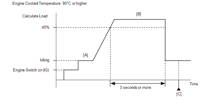
- Turn the engine switch on (IG).
- Turn the Techstream on.
- Clear the DTCs (even if no DTCs are stored, perform the clear DTC procedure).
- Turn the engine switch off and wait for at least 30 seconds.
- Start the engine and warm it up until the engine coolant temperature reaches 75°C (167°F) or higher [A].
- Turn the Techstream on.
- Enter the following menus: Powertrain / Engine / Data List / Calculate Load and Coolant Temperature.
-
Drive the vehicle for at least 3 seconds at the Calculate Load of 45% or more and the Coolant Temperature of 90°C (194°F) or higher [B].
CAUTION:
When performing the confirmation driving pattern, obey all speed limits and traffic laws.
- Stop the vehicle.
- Enter the following menus: Powertrain / Engine / Trouble Codes [C].
-
Read the pending DTCs.
HINT:
- If a pending DTC is output, the system is malfunctioning.
- If a pending DTC is not output, perform the following procedure.
- Enter the following menus: Powertrain / Engine / Utility / All Readiness.
- Input the DTC: P059712.
-
Check the DTC judgment result.
Techstream Display
Description
NORMAL
- DTC judgment completed
- System normal
ABNORMAL
- DTC judgment completed
- System abnormal
INCOMPLETE
- DTC judgment not completed
- Perform driving pattern after confirming DTC enabling conditions
HINT:
- If the judgment result is NORMAL, the system is normal.
- If the judgment result is ABNORMAL, the system has a malfunction.
-
[A] to [C]: Normal judgment procedure.
The normal judgment procedure is used to complete DTC judgment and also used when clearing permanent DTCs.
- When clearing the permanent DTCs, do not disconnect the cable from the battery terminal or attempt to clear the DTCs during this procedure, as doing so will clear the universal trip and normal judgment histories.
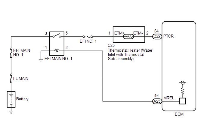
WIRING DIAGRAM
CAUTION / NOTICE / HINT
NOTICE:
Inspect the fuses for circuits related to this system before performing the following procedure.
HINT:
Read freeze frame data using the Techstream. The ECM records vehicle and driving condition information as freeze frame data the moment a DTC is stored. When troubleshooting, freeze frame data can help determine if the vehicle was moving or stationary, if the engine was warmed up or not, if the air fuel ratio was lean or rich, and other data from the time the malfunction occurred.
PROCEDURE
| 1. | CHECK HARNESS AND CONNECTOR (WATER INLET WITH THERMOSTAT SUB-ASSEMBLY - ECM) |
(a) Disconnect the water inlet with thermostat sub-assembly connector.
(b) Disconnect the ECM connector.
(c) Measure the resistance according to the value(s) in the table below.
Standard Resistance:
| Tester Connection | Condition | Specified Condition |
|---|---|---|
| C25-2 (ETM-) or C32-64 (PTCR) - Other terminals | Always | 10 kΩ or higher |
| OK | .gif) | REPLACE ECM |
| NG | | REPAIR OR REPLACE HARNESS OR CONNECTOR |
READ NEXT:
 Thermostat Heater Control Circuit Short to Ground or Open (P059714)
DESCRIPTION Refer to DTC P059712. Click here DTC No. Detection Item DTC Detection Condition Trouble Area MIL Memory Note P059714 Thermostat Heater Control Circuit Short to Groun
Internal Control Module Random Access Memory (RAM) Error Data Memory Failure (P060444)
MONITOR DESCRIPTION The ECM continuously monitors its internal memory status. This self-check ensures that the ECM is functioning properly. The ECM memory status is diagnosed by internal mirroring of
Control Module Performance Bank 2 Component Internal Failure (P060596,P060796)
MONITOR DESCRIPTION The ECM continuously monitors its internal processors (CPUs) and heated oxygen sensor transistors. This self-check ensures that the ECM is functioning properly. DTC No. Detect
SEE MORE:
How To Proceed With Troubleshooting
CAUTION / NOTICE / HINT HINT:
*: Use the Techstream
Use the following procedure to troubleshoot the hybrid control system.
PROCEDURE 1. VEHICLE BROUGHT TO WORKSHOP
NEXT 2. CUSTOMER PROBLEM ANALYSIS
NEXT 3. CONNECT TECHSTREAM TO THE DL
ECU Power Source Circuit System Voltage Low (B2620A2)
DESCRIPTION The ECU power source circuit supplies positive (+) voltage to the multiplex tilt and telescopic ECU. DTC No. Detection Item DTC Detection Condition Trouble Area B2620A2 ECU Power Source Circuit System Voltage Low The voltage of the ECU power source drops to 8 V or less f
