Lexus ES: Check Mode Procedure
CHECK MODE PROCEDURE
HINT:
Compared to normal mode, check mode is more sensitive to malfunctions. Therefore, check mode can detect malfunctions that cannot be detected in normal mode.
NOTICE:
All of the stored DTCs and Freeze Frame Data are cleared if: 1) the ECM is changed from normal mode to check mode or vice versa; or 2) the engine switch is turned from on (IG) to ACC or off while in check mode. Before changing modes, always check and note any DTCs and Freeze Frame Data.
CHECK MODE PROCEDURE
(a) Check and ensure the following conditions:
(1) Battery voltage is 11 V or higher.
(2) Accelerator pedal fully released.
(3) Shift lever is in P or N.
(4) A/C switch is off.
(b) Turn the engine switch off.
(c) Connect the Techstream to the DLC3.
(d) Turn the engine switch on (IG).
(e) Turn the Techstream on.
(f) Enter the following menus: Powertrain / Engine / Utility / Check Mode.
Powertrain > Engine > Utility| Tester Display |
|---|
| Check Mode |
(g) Change the ECM from normal mode to check mode.
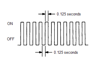
(h) Check that the MIL flashes as shown in the illustration.
(i) Start the engine.
(j) Check that the MIL turns off.
(k) Simulate the conditions of the malfunction described by the customer.
(l) Check for DTCs and Freeze Frame Data using the Techstream.
READ NEXT:
 Active Control Engine Mount System
DESCRIPTION LOCATION *1 Vacuum Switching Valve (for Active Control Engine Mount System) *2 Front Engine Mounting Insulator The active control engine mount system decreases engine vibratio
EVAP System
RELATED DTCS DTC No. SAE Monitoring Item Link P00FE00 P00FE EVAP vent line blocked P043E00 P043E Reference orifice clogged (built into canister pump module) P0
ECM Power Source Circuit
DESCRIPTION When the engine switch is turned on (IG), the battery voltage is applied to IGSW of the ECM. When the transistor in the MREL circuit operates, current flows from the battery to ground thro
SEE MORE:
Speed Signal Malfunction (B15C2)
DESCRIPTION The navigation ECU receives a vehicle speed signal from the combination meter assembly and information from the navigation antenna assembly, and then adjusts the vehicle position on the map. The navigation ECU stores this DTC when the difference between the speed information that the nav
Components
COMPONENTS ILLUSTRATION *1 FRONT WHEEL OPENING EXTENSION PAD RH *2 FRONT WHEEL OPENING EXTENSION PAD LH *3 NO. 1 ENGINE UNDER COVER *4 NO. 2 ENGINE UNDER COVER ASSEMBLY N*m (kgf*cm, ft.*lbf): Specified torque - - ILLUSTRATION *1 COOL AIR INTAKE DUCT SEAL *2
