Lexus ES: ECM Power Source Circuit
DESCRIPTION
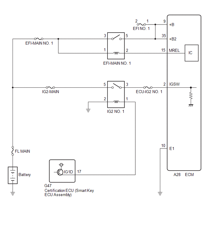
When the engine switch is turned on (IG), the battery voltage is applied to IGSW of the ECM. When the transistor in the MREL circuit operates, current flows from the battery to ground through the drive circuit of the EFI-MAIN NO. 1 relay, thus operating the relay which supplies power to the +B and +B2 terminals of the ECM.
WIRING DIAGRAM
CAUTION / NOTICE / HINT
NOTICE:
Inspect the fuses for circuits related to this system before performing the following procedure.
PROCEDURE
| 1. | CHECK HARNESS AND CONNECTOR (ECM - BODY GROUND) |
(a) Disconnect the ECM connector.
(b) Measure the resistance according to the value(s) in the table below.
Standard Resistance:
| Tester Connection | Condition | Specified Condition |
|---|---|---|
| A28-10 (E1) - Body ground | Always | Below 1 Ω |
| NG | .gif) | REPAIR OR REPLACE HARNESS OR CONNECTOR |
|
.gif)
| 2. | CHECK TERMINAL VOLTAGE (IGSW TERMINAL VOLTAGE) |
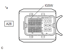
| *a | Front view of wire harness connector (to ECM) |
(a) Disconnect the ECM connector.
(b) Turn the engine switch on (IG).
(c) Measure the voltage according to the value(s) in the table below.
Standard Voltage:
| Tester Connection | Condition | Specified Condition |
|---|---|---|
| A28-2 (IGSW) - Body ground | Engine switch on (IG) | 11 to 14 V |
| NG | | GO TO STEP 6 |
|
| 3. | INSPECT EFI-MAIN NO. 1 RELAY |
(a) Inspect the EFI-MAIN NO. 1 relay.
Click here .gif)
| NG | | REPLACE EFI-MAIN NO. 1 RELAY |
|
| 4. | CHECK HARNESS AND CONNECTOR (EFI-MAIN NO. 1 RELAY - ECM) |
(a) Disconnect the ECM connector.
(b) Remove the EFI-MAIN NO. 1 relay from the No. 1 engine room relay block and No. 1 junction block assembly.
HINT:
Remove the VVT, EFI-MAIN NO. 2 and A/F HTR relays connected between the checked terminals as the coil inside the relay influences the measurement value.
(c) Measure the resistance according to the value(s) in the table below.
Standard Resistance:
| Tester Connection | Condition | Specified Condition |
|---|---|---|
| 2 (EFI-MAIN NO. 1 relay) - A28-15 (MREL) | Always | Below 1 Ω |
| 5 (EFI-MAIN NO. 1 relay) - A28-9 (+B) | Always | Below 1 Ω |
| 5 (EFI-MAIN NO. 1 relay) - A28-35 (+B2) | Always | Below 1 Ω |
| 2 (EFI-MAIN NO. 1 relay) or A28-15 (MREL) - Body ground and other terminals | Always | 10 kΩ or higher |
| 5 (EFI-MAIN NO. 1 relay), A28-9 (+B) or A28-35 (+B2) - Body ground and other terminals | Always | 10 kΩ or higher |
| NG | | REPAIR OR REPLACE HARNESS OR CONNECTOR |
|
| 5. | CHECK TERMINAL VOLTAGE (POWER SOURCE OF EFI-MAIN NO. 1 RELAY) |
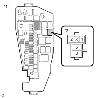
| *1 | No. 1 Engine Room Relay Block and No. 1 Junction Block Assembly |
| *2 | EFI-MAIN NO. 1 Relay |
(a) Remove the EFI-MAIN NO. 1 relay from the No. 1 engine room relay block and No. 1 junction block assembly.
(b) Measure the voltage according to the value(s) in the table below.
Standard Voltage:
| Tester Connection | Condition | Specified Condition |
|---|---|---|
| 3 (EFI-MAIN NO. 1 relay) - Body ground | Always | 11 to 14 V |
| 1 (EFI-MAIN NO. 1 relay) - Body ground | Always | 11 to 14 V |
| OK | | PROCEED TO NEXT SUSPECTED AREA SHOWN IN PROBLEM SYMPTOMS TABLE |
| NG | | REPAIR OR REPLACE HARNESS OR CONNECTOR (BATTERY - EFI-MAIN NO. 1 RELAY) |
| 6. | INSPECT IG2 NO. 1 RELAY |
(a) Inspect the IG2 NO. 1 relay.
Click here
| NG | | REPLACE IG2 NO. 1 RELAY |
|
| 7. | CHECK HARNESS AND CONNECTOR (IG2 NO. 1 RELAY - ECM) |
(a) Disconnect the ECM connector.
(b) Remove the IG2 NO. 1 relay from the No. 1 engine room relay block and No. 1 junction block assembly.
(c) Measure the resistance according to the value(s) in the table below.
Standard Resistance:
| Tester Connection | Condition | Specified Condition |
|---|---|---|
| 3 (IG2 NO. 1 relay) - A28-2 (IGSW) | Always | Below 1 Ω |
| 3 (IG2 NO. 1 relay) or A28-2 (IGSW) - Body ground and other terminals | Always | 10 kΩ or higher |
| NG | | REPAIR OR REPLACE HARNESS OR CONNECTOR |
|
| 8. | CHECK TERMINAL VOLTAGE (POWER SOURCE OF IG2 NO. 1 RELAY) |
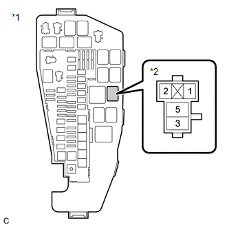
| *1 | No. 1 Engine Room Relay Block and No. 1 Junction Block Assembly |
| *2 | IG2 NO. 1 Relay |
(a) Remove the IG2 NO. 1 relay from the No. 1 engine room relay block and No. 1 junction block assembly.
(b) Measure the voltage according to the value(s) in the table below.
Standard Voltage:
| Tester Connection | Condition | Specified Condition |
|---|---|---|
| 5 (IG2 NO. 1 relay) - Body ground | Always | 11 to 14 V |
| NG | | REPAIR OR REPLACE HARNESS OR CONNECTOR (BATTERY - IG2 NO. 1 RELAY) |
|
| 9. | CHECK HARNESS AND CONNECTOR (IG2 NO. 1 RELAY - BODY GROUND) |
(a) Remove the IG2 NO. 1 relay from the No. 1 engine room relay block and No. 1 junction block assembly.
(b) Measure the resistance according to the value(s) in the table below.
Standard Resistance:
| Tester Connection | Condition | Specified Condition |
|---|---|---|
| 2 (IG2 NO. 1 relay) - Body ground | Always | Below 1 Ω |
| NG | | REPAIR OR REPLACE HARNESS OR CONNECTOR |
|
| 10. | CHECK HARNESS AND CONNECTOR (CERTIFICATION ECU (SMART KEY ECU ASSEMBLY) - IG2 NO. 1 RELAY) |
(a) Disconnect the certification ECU (smart key ECU assembly) connector.
(b) Remove the IG2 NO. 1 relay from the No. 1 engine room relay block and No. 1 junction block assembly.
(c) Measure the resistance according to the value(s) in the table below.
Standard Resistance:
| Tester Connection | Condition | Specified Condition |
|---|---|---|
| G47-17 (IG1D) - 1 (IG2 NO. 1 relay) | Always | Below 1 Ω |
| G47-17 (IG1D) or 1 (IG2 NO. 1 relay) - Body ground and other terminals | Always | 10 kΩ or higher |
| OK | | GO TO SMART KEY SYSTEM |
| NG | | REPAIR OR REPLACE HARNESS OR CONNECTOR |
READ NEXT:
 VC Output Circuit
DESCRIPTION The ECM constantly generates a 5 V power source voltage from the battery voltage supplied to the +B, +B2 (BATT) terminals to operate the microprocessor. The ECM also provides this power to
Starter Signal Circuit
DESCRIPTION While the engine is being cranked, current flows from terminal STAR of the certification ECU (smart key ECU assembly) to the park/neutral position switch assembly and to terminal STA of th
Brake Override System
DESCRIPTION When the vehicle is being driven, depressing the accelerator pedal sensor assembly and brake pedal will activate the brake override system to restrict engine output. The conditions for act
SEE MORE:
Headlight LH Circuit (B2439,B243A)
DESCRIPTION The headlight ECU sub-assembly LH and headlight ECU sub-assembly RH internally boost the power supply voltage to ensure a constant supplied current for the lo/hi beam LED of their respective headlight. By monitoring the LED power supply voltage, abnormal current and malfunctions can be d
Reassembly
REASSEMBLY PROCEDURE 1. INSTALL FRONT BUMPER SIDE SUPPORT LH (a) Engage the clip as shown in the illustration. Install in this Direction (b) Install the front bumper side support LH with the bolt. Torque: 5.4 N·m {55 kgf·cm, 48 in·lbf} 2. INSTALL FRONT BUMPER SIDE SUPPOR
