Lexus ES: Active Control Engine Mount System
DESCRIPTION
LOCATION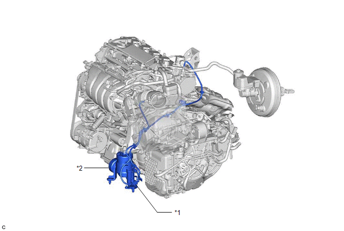
| *1 | Vacuum Switching Valve (for Active Control Engine Mount System) | *2 | Front Engine Mounting Insulator |
The active control engine mount system decreases engine vibration at a low engine speed using the vacuum switching valve (for active control engine mount system). The vacuum switching valve (for active control engine mount system) is controlled by a pulse signal transmitted to the vacuum switching valve (for active control engine mount system) from the ECM. The frequency of this pulse signal is matched to the engine speed to decrease engine vibration.
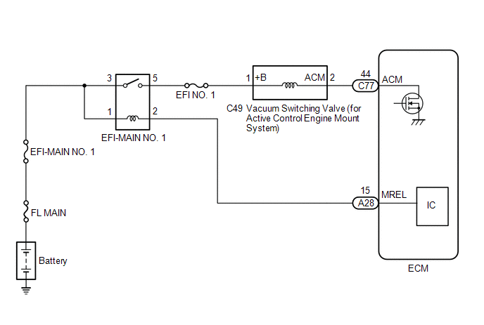
WIRING DIAGRAM
CAUTION / NOTICE / HINT
NOTICE:
Inspect the fuses for circuits related to this system before performing the following procedure.
PROCEDURE
| 1. | PERFORM ACTIVE TEST USING TECHSTREAM (ACTIVATE THE ACM INHIBIT) |
(a) Connect the Techstream to the DLC3.
(b) Turn the engine switch on (IG).
(c) Turn the Techstream on.
(d) Enter the following menus: Powertrain / Engine / Active Test / Activate the ACM Inhibit.
Powertrain > Engine > Active Test| Tester Display |
|---|
| Activate the ACM Inhibit |
(e) According to the display on the Techstream, perform the Active Test to operate the vacuum switching valve (for active control engine mount system) and for check the operating sound of the vacuum switching valve (for active control engine mount system).
OK:
Operating sounds can be heard.
| NG | .gif) | GO TO STEP 5 |
|
.gif)
| 2. | CHECK VACUUM HOSES |
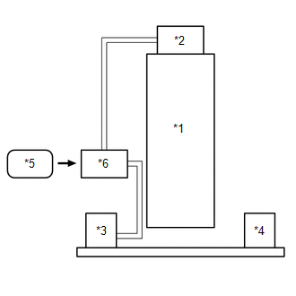
| *1 | Engine |
| *2 | Vacuum Pump Assembly |
| *3 | Front Engine Mounting Insulator |
| *4 | Rear Engine Mounting Insulator |
| *5 | ECM |
| *6 | Vacuum Switching Valve (for Active Control Engine Mount System) |
(a) Check the air and vacuum hoses for looseness, disconnection and blockage.
OK:
No looseness, disconnection or blockage.
| NG | | REPAIR OR REPLACE VACUUM HOSES |
|
| 3. | CHECK VACUUM |
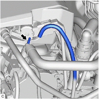
(a) Disconnect the vacuum hose from the vacuum pump assembly.
(b) Start the engine.
(c) Check that the disconnected port located on the vacuum pump assembly applies suction to your finger.
OK:
Vacuum exists.
| NG | | REPLACE VACUUM PUMP ASSEMBLY |
|
| 4. | INSPECT FRONT ENGINE MOUNTING INSULATOR |
(a) Inspect the front engine mounting insulator.
Click here .gif)
| OK | | SYSTEM NORMAL |
| NG | | REPLACE FRONT ENGINE MOUNTING INSULATOR |
| 5. | CHECK TERMINAL VOLTAGE (POWER SOURCE OF VACUUM SWITCHING VALVE (FOR ACTIVE CONTROL ENGINE MOUNT SYSTEM)) |
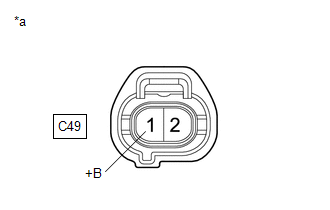
| *a | Front view of wire harness connector (to Vacuum Switching Valve (for Active Control Engine Mount System)) |
(a) Disconnect the vacuum switching valve (for active control engine mount system) connector.
(b) Turn the engine switch on (IG).
(c) Measure the voltage according to the value(s) in the table below.
Standard Voltage:
| Tester Connection | Condition | Specified Condition |
|---|---|---|
| C49-1 (+B) - Body ground | Engine switch on (IG) | 11 to 14 V |
| NG | | GO TO ECM POWER SOURCE CIRCUIT |
|
| 6. | INSPECT VACUUM SWITCHING VALVE (FOR ACTIVE CONTROL ENGINE MOUNT SYSTEM) |
(a) Inspect the vacuum switching valve (for active control engine mount system).
Click here
| NG | | REPLACE VACUUM SWITCHING VALVE (FOR ACTIVE CONTROL ENGINE MOUNT SYSTEM) |
|
| 7. | CHECK HARNESS AND CONNECTOR (VACUUM SWITCHING VALVE (FOR ACTIVE CONTROL ENGINE MOUNT SYSTEM) - ECM) |
(a) Disconnect the vacuum switching valve (for active control engine mount system) connector.
(b) Disconnect the ECM connector.
(c) Measure the resistance according to the value(s) in the table below.
Standard Resistance:
| Tester Connection | Condition | Specified Condition |
|---|---|---|
| C49-2 (ACM) - C77-44 (ACM) | Always | Below 1 Ω |
| C49-2 (ACM) or C77-44 (ACM) - Body ground and other terminals | Always | 10 kΩ or higher |
| OK | | REPLACE ECM |
| NG | | REPAIR OR REPLACE HARNESS OR CONNECTOR |
READ NEXT:
 EVAP System
RELATED DTCS DTC No. SAE Monitoring Item Link P00FE00 P00FE EVAP vent line blocked P043E00 P043E Reference orifice clogged (built into canister pump module) P0
ECM Power Source Circuit
DESCRIPTION When the engine switch is turned on (IG), the battery voltage is applied to IGSW of the ECM. When the transistor in the MREL circuit operates, current flows from the battery to ground thro
VC Output Circuit
DESCRIPTION The ECM constantly generates a 5 V power source voltage from the battery voltage supplied to the +B, +B2 (BATT) terminals to operate the microprocessor. The ECM also provides this power to
SEE MORE:
Inspection
INSPECTION PROCEDURE 1. INSPECT ENGINE OIL LEVEL SENSOR (a) Measure the resistance according to the value(s) in the table below. Standard Resistance: Tester Connection Condition Specified Condition 1 - Engine Oil Level Sensor Body ON Below 1 Ω OFF 10 kΩ or higher If the
ECU Malfunction (C1611)
DESCRIPTION This DTC is stored if the rear television camera assembly judges that there is an internal malfunction as a result of its self check. HINT: The rear television camera assembly stores different types of information during initialization. If the rear television camera assembly cannot read
