Lexus ES: Check Bus 5 Line for Short to GND
DESCRIPTION
There may be a short circuit between one of the CAN bus lines and GND when there is no resistance between terminal 15 (CA5H) of the central gateway ECU (network gateway ECU) and terminal 4 (CG) of the DLC3, or terminal 16 (CA5L) of the central gateway ECU (network gateway ECU) and terminal 4 (CG) of the DLC3.
| Symptom | Trouble Area |
|---|---|
| There is no resistance between terminal 15 (CA5H) of the central gateway ECU (network gateway ECU) and terminal 4 (CG) of the DLC3, or terminal 16 (CA5L) of the central gateway ECU (network gateway ECU) and terminal 4 (CG) of the DLC3. |
|
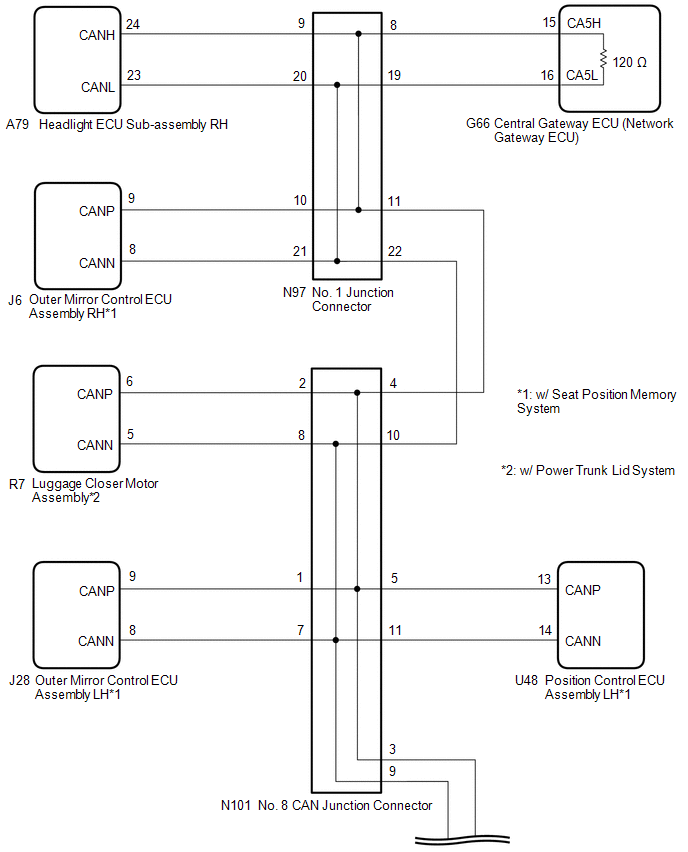
WIRING DIAGRAM
CAUTION / NOTICE / HINT
CAUTION:
When performing the confirmation driving pattern, obey all speed limits and traffic laws.
NOTICE:
-
Because the order of diagnosis is important to allow correct diagnosis, make sure to begin troubleshooting using How to Proceed with Troubleshooting when CAN communication system related DTCs are output.
Click here
.gif)
- Before measuring the resistance of the CAN bus, turn the engine switch off and leave the vehicle for 1 minute or more without operating the key or any switches, or opening or closing the doors. After that, disconnect the cable from the negative (-) battery terminal and leave the vehicle for 1 minute or more before measuring the resistance.
-
After turning the engine switch off, waiting time may be required before disconnecting the cable from the negative (-) battery terminal. Therefore, make sure to read the disconnecting the cable from the negative (-) battery terminal notices before proceeding with work.
Click here
-
After performing repairs, perform the DTC check procedure and confirm that the DTCs are not output again.
DTC check procedure: Turn the engine switch on (IG) and wait for 1 minute or more. Then operate the suspected malfunctioning system and drive the vehicle at 60 km/h (37 mph) or more for 5 minutes or more.
-
After the repair, perform the CAN bus check and check that all the ECUs and sensors connected to the CAN communication system are displayed as normal.
Click here
-
Before replacing the main body ECU (multiplex network body ECU) or certification ECU (smart key ECU assembly), refer to Registration.
Click here
HINT:
- Before disconnecting related connectors for inspection, push in on each connector body to check that the connector is not loose or disconnected.
- When a connector is disconnected, check that the terminals and connector body are not cracked, deformed or corroded.
PROCEDURE
| 1. | CHECK FOR SHORT TO GND IN CAN BUS LINE (NO. 1 JUNCTION CONNECTOR) |
(a) Disconnect the cable from the negative (-) battery terminal.
(b) Disconnect the N97 No. 1 junction connector.
(c) Measure the resistance according to the value(s) in the table below.
.png)
| *1 | DLC3 | - | - |
| *a | Front view of wire harness connector (to No. 1 Junction Connector) | *b | to Central Gateway ECU (Network Gateway ECU) |
| *c | to Headlight ECU Sub-assembly RH | *d | to Outer Mirror Control ECU Assembly RH (w/ Seat Position Memory System) |
| *e | to No. 8 CAN Junction Connector | - | - |
Standard Resistance:
| Tester Connection | Condition | Specified Condition | Connected to |
|---|---|---|---|
| N97-8 (CANH) - G57-4 (CG) | Cable disconnected from negative (-) battery terminal | 200 Ω or higher | Central gateway ECU (network gateway ECU) |
| N97-19 (CANL) - G57-4 (CG) | |||
| N97-9 (CANH) - G57-4 (CG) | Cable disconnected from negative (-) battery terminal | 200 Ω or higher | Headlight ECU sub-assembly RH |
| N97-20 (CANL) - G57-4 (CG) | |||
| N97-10 (CANH) - G57-4 (CG) | Cable disconnected from negative (-) battery terminal | 200 Ω or higher | Outer mirror control ECU assembly RH* |
| N97-21 (CANL) - G57-4 (CG) | |||
| N97-11 (CANH) - G57-4 (CG) | Cable disconnected from negative (-) battery terminal | 200 Ω or higher | No. 8 CAN junction connector |
| N97-22 (CANL) - G57-4 (CG) |
- *: w/ Seat Position Memory System
| Result | Proceed to |
|---|---|
| OK | A |
| NG (Line to central gateway ECU (network gateway ECU)) | B |
| NG (Line to No. 8 CAN junction connector) | C |
| NG (Line to ECU or sensor) | D |
| A | .gif) | REPLACE NO. 1 JUNCTION CONNECTOR |
| C | | GO TO STEP 3 |
| D | | GO TO STEP 5 |
|
.gif)
| 2. | CHECK FOR SHORT TO GND IN CAN BUS LINE (NO. 1 JUNCTION CONNECTOR - CENTRAL GATEWAY ECU (NETWORK GATEWAY ECU)) |
(a) Disconnect the G66 central gateway ECU (network gateway ECU) connector.
(b) Measure the resistance according to the value(s) in the table below.
.png)
| *1 | DLC3 | - | - |
| *a | Front view of wire harness connector (to No. 1 Junction Connector) | *b | to Central Gateway ECU (Network Gateway ECU) |
Standard Resistance:
| Tester Connection | Condition | Specified Condition |
|---|---|---|
| N97-8 (CANH) - G57-4 (CG) | Cable disconnected from negative (-) battery terminal | 200 Ω or higher |
| N97-19 (CANL) - G57-4 (CG) |
| OK | | REPLACE CENTRAL GATEWAY ECU (NETWORK GATEWAY ECU) |
| NG | | REPAIR OR REPLACE CAN MAIN BUS LINE OR CONNECTOR (NO. 1 JUNCTION CONNECTOR - CENTRAL GATEWAY ECU (NETWORK GATEWAY ECU)) |
| 3. | CHECK FOR SHORT TO GND IN CAN BUS LINE (NO. 8 CAN JUNCTION CONNECTOR) |
(a) Disconnect the N101 No. 8 CAN junction connector.
(b) Measure the resistance according to the value(s) in the table below.
.png)
| *1 | DLC3 | - | - |
| *a | Front view of wire harness connector (to No. 8 CAN Junction Connector) | *b | to Outer Mirror Control ECU Assembly LH (w/ Seat Position Memory System) |
| *c | to Luggage Closer Motor Assembly (w/ Power Trunk Lid System) | *d | to No. 5 CAN Junction Connector |
| *e | to No. 1 Junction Connector | *f | to Position Control ECU Assembly LH (w/ Seat Position Memory System) |
Standard Resistance:
| Tester Connection | Condition | Specified Condition | Connected to |
|---|---|---|---|
| N101-1 (CANH) - G57-4 (CG) | Cable disconnected from negative (-) battery terminal | 200 Ω or higher | Outer mirror control ECU assembly LH*1 |
| N101-7 (CANL) - G57-4 (CG) | |||
| N101-2 (CANH) - G57-4 (CG) | Cable disconnected from negative (-) battery terminal | 200 Ω or higher | Luggage closer motor assembly*2 |
| N101-8 (CANL) - G57-4 (CG) | |||
| N101-3 (CANH) - G57-4 (CG) | Cable disconnected from negative (-) battery terminal | 200 Ω or higher | No. 5 CAN junction connector |
| N101-9 (CANL) - G57-4 (CG) | |||
| N101-4 (CANH) - G57-4 (CG) | Cable disconnected from negative (-) battery terminal | 200 Ω or higher | No. 1 junction connector |
| N101-10 (CANL) - G57-4 (CG) | |||
| N101-5 (CANH) - G57-4 (CG) | Cable disconnected from negative (-) battery terminal | 200 Ω or higher | Position control ECU assembly LH*1 |
| N101-11 (CANL) - G57-4 (CG) |
- *1: w/ Seat Position Memory System
- *2: w/ Power Trunk Lid System
| Result | Proceed to |
|---|---|
| OK | A |
| NG (Line to No. 1 junction connector) | B |
| NG (Line to No. 5 CAN junction connector) | C |
| NG (Line to ECU or sensor) | D |
| A | | REPLACE NO. 8 CAN JUNCTION CONNECTOR |
| B | | REPAIR OR REPLACE CAN MAIN BUS LINE OR CONNECTOR (NO. 8 CAN JUNCTION CONNECTOR - NO. 1 JUNCTION CONNECTOR) |
| D | | GO TO STEP 5 |
|
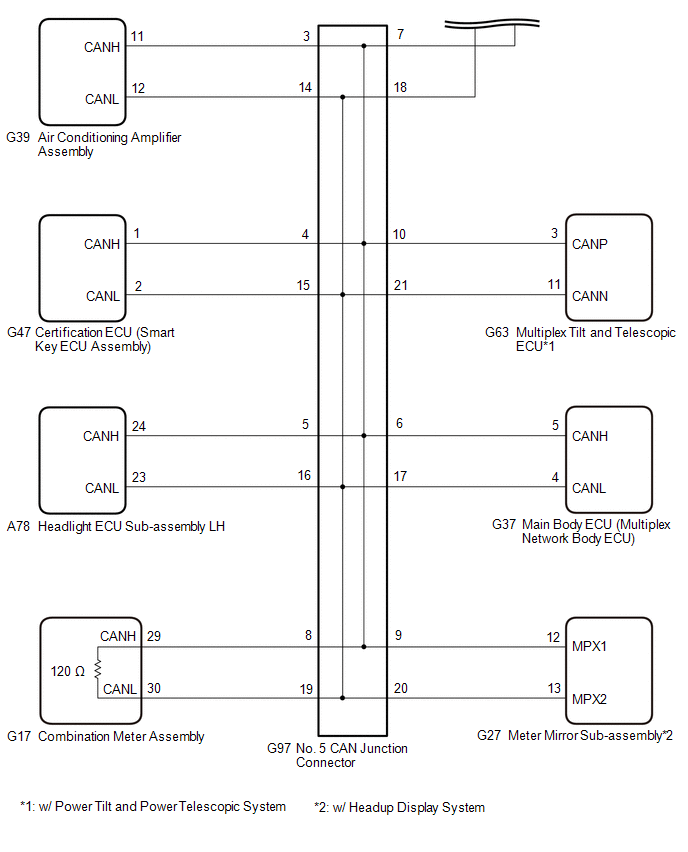
| 4. | CHECK FOR SHORT TO GND IN CAN BUS LINE (NO. 5 CAN JUNCTION CONNECTOR) |
(a) Disconnect the G97 No. 5 CAN junction connector.
(b) Measure the resistance according to the value(s) in the table below.
.png)
| *1 | DLC3 | - | - |
| *a | Front view of wire harness connector (to No. 5 CAN Junction Connector) | *b | to Air Conditioning Amplifier Assembly |
| *c | to Certification ECU (Smart Key ECU Assembly) | *d | to Headlight ECU Sub-assembly LH |
| *e | to Main Body ECU (Multiplex Network Body ECU) | *f | to No. 8 CAN Junction Connector |
| *g | to Combination Meter Assembly | *h | to Meter Mirror Sub-assembly (w/ Headup Display System) |
| *i | to Multiplex Tilt and Telescopic ECU (w/ Power Tilt and Power Telescopic System) | - | - |
Standard Resistance:
| Tester Connection | Condition | Specified Condition | Connected to |
|---|---|---|---|
| G97-3 (CANH) - G57-4 (CG) | Cable disconnected from negative (-) battery terminal | 200 Ω or higher | Air conditioning amplifier assembly |
| G97-14 (CANL) - G57-4 (CG) | |||
| G97-4 (CANH) - G57-4 (CG) | Cable disconnected from negative (-) battery terminal | 200 Ω or higher | Certification ECU (smart key ECU assembly) |
| G97-15 (CANL) - G57-4 (CG) | |||
| G97-5 (CANH) - G57-4 (CG) | Cable disconnected from negative (-) battery terminal | 200 Ω or higher | Headlight ECU sub-assembly LH |
| G97-16 (CANL) - G57-4 (CG) | |||
| G97-6 (CANH) - G57-4 (CG) | Cable disconnected from negative (-) battery terminal | 200 Ω or higher | Main body ECU (multiplex network body ECU) |
| G97-17 (CANL) - G57-4 (CG) | |||
| G97-7 (CANH) - G57-4 (CG) | Cable disconnected from negative (-) battery terminal | 200 Ω or higher | No. 8 CAN junction connector |
| G97-18 (CANL) - G57-4 (CG) | |||
| G97-8 (CANH) - G57-4 (CG) | Cable disconnected from negative (-) battery terminal | 200 Ω or higher | Combination meter assembly |
| G97-19 (CANL) - G57-4 (CG) | |||
| G97-9 (CANH) - G57-4 (CG) | Cable disconnected from negative (-) battery terminal | 200 Ω or higher | Meter mirror sub-assembly*1 |
| G97-20 (CANL) - G57-4 (CG) | |||
| G97-10 (CANH) - G57-4 (CG) | Cable disconnected from negative (-) battery terminal | 200 Ω or higher | Multiplex tilt and telescopic ECU*2 |
| G97-21 (CANL) - G57-4 (CG) |
- *1: w/ Headup Display System
- *2: w/ Power Tilt and Power Telescopic System
| Result | Proceed to |
|---|---|
| OK | A |
| NG (Line to No. 8 CAN junction connector) | B |
| NG (Line to ECU or sensor) | C |
| A | | REPLACE NO. 5 CAN JUNCTION CONNECTOR |
| B | | REPAIR OR REPLACE CAN MAIN BUS LINE OR CONNECTOR (NO. 5 CAN JUNCTION CONNECTOR - NO. 8 CAN JUNCTION CONNECTOR) |
| C | | GO TO STEP 5 |
| 5. | CHECK FOR SHORT TO GND IN CAN BUS LINE (ECU OR SENSOR) |
(a) Reconnect all wire harness connectors.
(b) Disconnect the connector that includes terminals CANH and CANL from the ECU or sensor to which the bus line shorted to GND is connected.
Click here
(c) Measure the resistance according to the value(s) in the table below.
.png)
| *1 | DLC3 | - | - |
| *a | Component with harness connected (Central Gateway ECU (Network Gateway ECU)) | - | - |
Standard Resistance:
| Tester Connection | Condition | Specified Condition |
|---|---|---|
| G66-15 (CA5H) - G57-4 (CG) | Cable disconnected from negative (-) battery terminal | 200 Ω or higher |
| G66-16 (CA5L) - G57-4 (CG) |
HINT:
- If the resistance changes to 200 Ω or higher when the connector is disconnected from the ECU or sensor, there may be a short in the ECU or sensor.
- If the resistance does not become normal when the connector is disconnected from the ECU or sensor, check for a short to ground in the wire harness and repair or replace the wire harness or connector if necessary.
| OK | | REPLACE ECU OR SENSOR |
| NG | | REPAIR OR REPLACE HARNESS OR CONNECTOR |
READ NEXT:
 Check Bus 5 Line for Short to +B
DESCRIPTION There may be a short circuit between one of the CAN bus lines and +B when there is no resistance between terminal 15 (CA5H) of the central gateway ECU (network gateway ECU) and terminal 16
Check Bus 5 Lines for Short Circuit
DESCRIPTION There may be a short circuit between the CAN main bus lines and/or CAN branch lines when the resistance between terminals 15 (CA5H) and 16 (CA5L) of the central gateway ECU (network gatewa
Open in Bus 5 Main Bus Line
DESCRIPTION There may be an open circuit in one of the CAN main bus lines when the resistance between terminals 15 (CA5H) and 16 (CA5L) of the central gateway ECU (network gateway ECU) is 70 Ω or hig
SEE MORE:
Components
COMPONENTS ILLUSTRATION *A for TMC Made *B Type A *C Type B - - *1 COMPRESSOR ASSEMBLY WITH MAGNETIC CLUTCH *2 DRIVE SHAFT BEARING BRACKET *3 ENGINE COVER BRACKET *4 ENGINE OIL LEVEL DIPSTICK GUIDE *5 GENERATOR ASSEMBLY *6 IGNITION COIL ASSEMBLY
Removal
REMOVAL CAUTION / NOTICE / HINT The necessary procedures (adjustment, calibration, initialization or registration) that must be performed after parts are removed and installed, or replaced during heated oxygen sensor removal/installation are shown below. Necessary Procedures After Parts Removed/Inst
