Lexus ES: Buzzer does not Sound
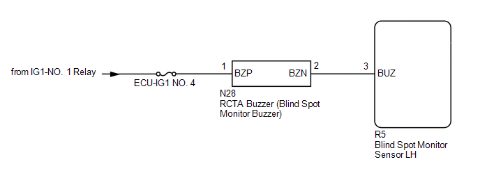
WIRING DIAGRAM
CAUTION / NOTICE / HINT
NOTICE:
- When checking for DTCs, make sure that the blind spot monitor system is turned on.
- Inspect the fuses for circuits related to this system before performing the following procedure.
PROCEDURE
| 1. | CHECK DTC |
(a) Turn the engine switch off.
(b) Turn the engine switch on (IG).
(c) Recheck for DTCs and check if the same DTC is output again.
Body Electrical > Blind Spot Monitor Slave > Trouble CodesOK:
No DTCs are output.
| NG | .gif) | GO TO DTC CHART |
|
.gif)
| 2. | CHECK HARNESS AND CONNECTOR (RCTA BUZZER - BLIND SPOT MONITOR SENSOR LH) |
(a) Disconnect the N28 RCTA buzzer (blind spot monitor buzzer) connector.
(b) Measure the voltage according to the value(s) in the table below.
Standard Voltage:
| Tester Connection | Switch Condition | Specified Condition |
|---|---|---|
| N28-1 (BZP) - Body ground | Engine Switch on (IG) | 11 to 14 V |
| N28-2 (BZN) or R5-3 (BUZ) - Body ground | Below 1 V | |
| N28-2 (BZN) - N28-1 (BZP) | Below 1 V |
| NG | | REPAIR OR REPLACE HARNESS OR CONNECTOR |
|
| 3. | CHECK HARNESS AND CONNECTOR (RCTA BUZZER - BLIND SPOT MONITOR SENSOR LH AND BATTERY) |
(a) Disconnect the N28 RCTA buzzer (blind spot monitor buzzer) connector.
(b) Disconnect the R5 blind spot monitor sensor LH connector.
(c) Measure the resistance according to the value(s) in the table below.
Standard Resistance:
| Tester Connection | Condition | Specified Condition |
|---|---|---|
| N28-2 (BZN) - R5-3 (BUZ) | Always | Below 1 Ω |
| N28-2 (BZN) or R5-3 (BUZ) - Body ground | Always | 10 kΩ or higher |
(d) Measure the voltage according to the value(s) in the table below.
Standard Voltage:
| Tester Connection | Switch Condition | Specified Condition |
|---|---|---|
| N28-2 (BZN) or R5-3 (BUZ) - Body ground | Engine switch on (IG) | Below 1 V |
| N28-1 (BZP) - Body ground | Engine switch on (IG) | 11 to 14 V |
| N28-1 (BZP) - Body ground | Engine switch off | Below 1 V |
| OK | | REPLACE BLIND SPOT MONITOR BUZZER |
| NG | | REPAIR OR REPLACE HARNESS OR CONNECTOR |
READ NEXT:
 Front Left Sensor Malfunction (C1AE1)
DESCRIPTION The front corner ultrasonic sensor LH is installed to the front bumper. The clearance warning ECU assembly detects obstacles based on signals received from the front corner ultrasonic sens
Front Left Center Sensor (C1AE2)
DESCRIPTION The front center ultrasonic sensor LH is installed to the front bumper. The clearance warning ECU assembly detects obstacles based on signals received from the front center ultrasonic sens
Front Right Center Sensor (C1AE3)
DESCRIPTION The front center ultrasonic sensor RH is installed to the front bumper. The clearance warning ECU assembly detects obstacles based on signals received from the front center ultrasonic sens
SEE MORE:
Check For Intermittent Problems
CHECK FOR INTERMITTENT PROBLEMS NOTICE:
If the vehicle or vehicle controls are operated (for example, during initial inspection when the vehicle is brought in for repair) before operation history has been read and saved, the operation history information could be lost.
The operation history fun
System Description
SYSTEM DESCRIPTION GENERAL (a) The rear window defogger wire (back window glass) is attached to the inside of the rear window and defogs the window surface quickly when the rear window defogger switch is pressed. The indicator light on the switch illuminates while the system is operating. This syste
