Lexus ES: Adjustment
ADJUSTMENT
CAUTION / NOTICE / HINT
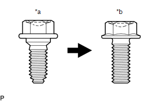
| *a | Centering Bolt |
| *b | Standard Bolt |
HINT:
- Centering bolts are used to install the hood hinges and hood lock. The hood and hood lock cannot be adjusted with the centering bolts installed. Substitute the centering bolts with standard bolts with washers when making adjustments.
-
The specified torque for standard bolts is shown in the standard bolt chart.
Click here
.gif)
PROCEDURE
1. INSPECT HOOD SUB-ASSEMBLY
Click here
2. ADJUST HOOD SUB-ASSEMBLY
(a) Horizontally and vertically adjust the hood.
| (1) Loosen the 4 hinge bolts of the hood. |
|
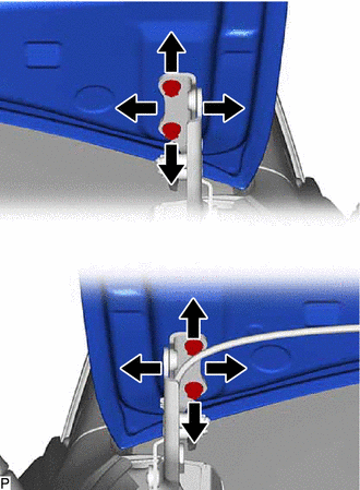
(2) Adjust the clearance between the hood and front fenders by moving the hood.
(3) Tighten the 4 hinge bolts after adjustment.
Torque:
13 N·m {133 kgf·cm, 10 ft·lbf}
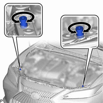
(b) Adjust the height of the front end of the hood using the hood bumper cushions.
| (1) Adjust the 2 hood bumper cushions so that the heights of the hood and fenders are aligned. HINT: Raise or lower the front end of the hood by turning the 2 hood bumper cushions. |
|
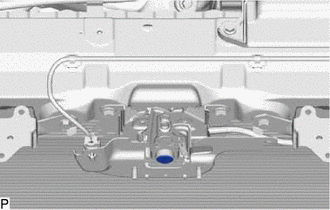
(c) Adjust the hood lock.
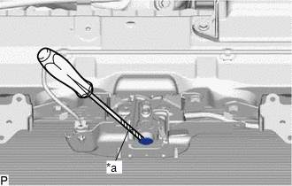
(1) Remove the cool air intake duct seal.
Click here
| (2) Using a screwdriver with its tip wrapped with protective tape, remove the hood lock nut cap. |
|
| (3) Loosen the 2 bolts and hood lock bolt. |
|
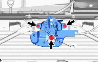
| (4) Adjust the hood lock assembly and tighten the 2 bolts and hood lock bolt. Torque: 7.5 N·m {76 kgf·cm, 66 in·lbf} |
|

(5) Check that the striker can engage the hood lock assembly smoothly.
| (6) Install a new hood lock nut cap. |
|
(7) Install the cool air intake duct seal.
Click here
READ NEXT:
 Reassembly
REASSEMBLY PROCEDURE 1. INSTALL HOOD STAY BRACKET LH Click here 2. INSTALL HOOD STAY BRACKET RH HINT: Use the same procedure as for the LH side. 3. INSTALL HOOD SUPPORT ASSEMBLY LH Click here 4. I
Components
COMPONENTS ILLUSTRATION *A for HV Model - - *1 COOL AIR INTAKE DUCT SEAL *2 FRONT FENDER LINER RETAINER *3 FRONT WHEEL OPENING EXTENSION PAD LH *4 HOOD LOCK ASSEMBLY
SEE MORE:
Components
COMPONENTS ILLUSTRATION *1 NO. 1 ENGINE UNDER COVER *2 NO. 2 ENGINE UNDER COVER ASSEMBLY *3 FRONT WHEEL OPENING EXTENSION PAD LH *4 FRONT WHEEL OPENING EXTENSION PAD RH *5 FRONT FENDER APRON SEAL LH - - N*m (kgf*cm, ft.*lbf): Specified torque - - ILLUSTRAT
Parts Location
PARTS LOCATION ILLUSTRATION *1 FRONT ABSORBER CONTROL ACTUATOR RH (FRONT SHOCK ABSORBER ASSEMBLY RH) *2 FRONT ABSORBER CONTROL ACTUATOR LH (FRONT SHOCK ABSORBER ASSEMBLY LH) *3 REAR ABSORBER CONTROL ACTUATOR RH (REAR SHOCK ABSORBER ASSEMBLY RH) *4 REAR ABSORBER CONTROL ACTUATOR L
