Lexus ES: Adjustment
ADJUSTMENT
PROCEDURE
1. STEERING WHEEL OFF CENTER ADJUSTMENT PROCEDURE
(a) Inspect steering wheel off center.
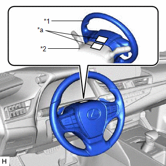
(1) Turn the steering wheel assembly to the center position.
| (2) Apply masking tape to the top center of the steering wheel assembly and upper steering column cover. |
|
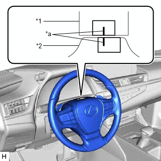
(3) Drive the vehicle in a straight line for 100 m (328 ft.) at a constant speed of 56 km/h (35 mph), while holding the steering wheel assembly to maintain the course.
| (4) Draw a line on the masking tape as shown in the illustration. |
|
(5) Turn the steering wheel assembly to the center position.
| (6) Draw a new line on the masking tape on the steering wheel assembly as shown in the illustration. |
|
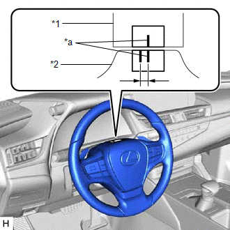
(7) Measure the distance between the 2 lines on the masking tape on the steering wheel assembly.
(8) Convert the measured distance to the steering angle.
HINT:
- Measured distance of 1 mm (0.0394 in.) = Steering angle of approximately 1 degree
- Make a note of the steering angle.
(b) Adjust the steering angle.
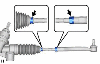
| (1) Put matchmarks on the tie rod assemblies LH and RH and steering rack end sub-assembly respectively. |
|
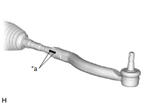
(2) Using a paper gauge, measure the thread length of the steering rack end sub-assemblies.
HINT:
- Measure both RH and LH sides.
- Make a note of the measured values.
| (3) Remove the steering rack boot clips from the RH and LH steering rack boots. |
|
(4) Loosen the RH and LH lock nuts.
(5) Turn the RH and LH steering rack end sub-assemblies by the same amount (but in different directions) according to the measured steering angle.
HINT:
One 360 degree turn of a steering rack end sub-assembly (1.5 mm (0.0591 in.) horizontal movement) equals 9.2 degrees of steering angle.
(6) Tighten the RH and LH lock nuts to the specified torque.
Torque:
88 N·m {897 kgf·cm, 65 ft·lbf}
NOTICE:
Make sure that the difference in thread length between the RH and LH steering rack end sub-assemblies is within 1.5 mm (0.0591 in.).
(7) Install the RH and LH steering rack boot clips.
HINT:
Make sure that the tabs of the RH and LH steering rack boot clips are positioned within the area shown in the illustration.
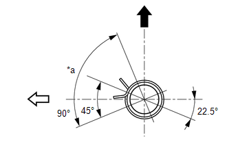
| *a | Clip Tab Positioning Area |
 | Up |
 | Rear of Vehicle |
READ NEXT:
 Components
COMPONENTS ILLUSTRATION *1 STEERING WHEEL ASSEMBLY - - Tightening torque for "Major areas involving basic vehicle performance such as moving/turning/stopping": N*m (kgf*cm, ft.*lbf)
Removal
REMOVAL CAUTION / NOTICE / HINT The necessary procedures (adjustment, calibration, initialization or registration) that must be performed after parts are removed and installed, or replaced during stee
SEE MORE:
LTA (Lane Tracing Assist)
When driving on highways and
freeways with white (yellow) lane
lines, this function alerts the driver
when the vehicle might depart from
its lane or course* and provides
assistance by operating the steering
wheel to keep the vehicle in its
lane or course*. Furthermore, the
system provides st
Installation
INSTALLATION PROCEDURE 1. INSTALL LEVEL WARNING SWITCH ASSEMBLY (a) Install the level warning switch assembly as shown in the illustration. *a Protrusion *b Marking Install in this Direction NOTICE: Make sure that the protrusion of the level warning switch is between the 2 mark
