Lexus ES: ACIS Control Circuit
DESCRIPTION
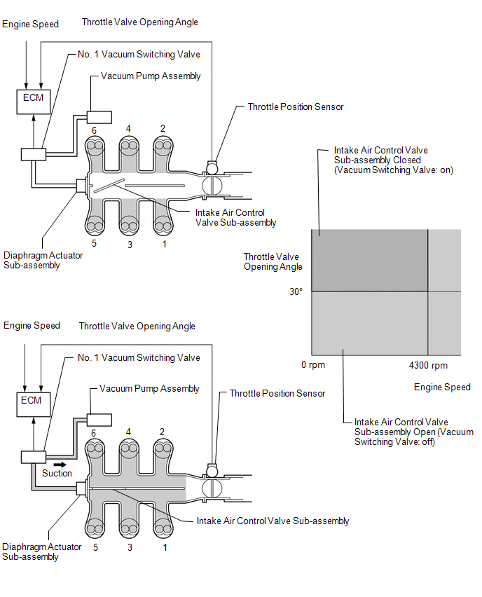
ACIS (Acoustic Control Induction System) controls the opening and closing the intake air control valve sub-assembly built into the intake air surge tank assembly to increase the intake efficiency according to the engine load.
When the engine speed is between 0 and 4300 rpm and the throttle valve opening angle is 30° or more, the ECM activates the No. 1 vacuum switching valve (for intake air control valve sub-assembly) which then applies vacuum from the vacuum pump assembly to the diaphragm actuator sub-assembly and closes the intake air control valve sub-assembly.
When the engine speed and/or throttle valve opening angle are not as specified above, the ECM deactivates the No. 1 vacuum switching valve (for intake air control valve sub-assembly), causing the intake air control valve sub-assembly to open.
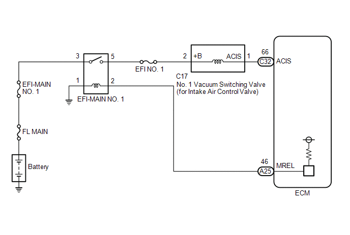
WIRING DIAGRAM
CAUTION / NOTICE / HINT
NOTICE:
Inspect the fuses for circuits related to this system before performing the following procedure.
PROCEDURE
| 1. | PERFORM ACTIVE TEST USING TECHSTREAM (ACTIVATE THE VSV FOR INTAKE CONTROL) |
(a) Connect the Techstream to the DLC3.
(b) Start the engine.
(c) Turn the Techstream on.
(d) Enter the following menus: Powertrain / Engine / Active Test / Activate the VSV for Intake Control.
Powertrain > Engine > Active Test| Tester Display |
|---|
| Activate the VSV for Intake Control |
(e) According to the display on the Techstream, perform the Active Test to operate the No. 1 vacuum switching valve (for intake air control valve sub-assembly) and check for the operating sound of the intake air control valve sub-assembly in the intake air surge tank assembly.
OK:
Operating sounds can be heard.
| OK | .gif) | PROCEED TO NEXT SUSPECTED AREA SHOWN IN PROBLEM SYMPTOMS TABLE |
|
.gif)
| 2. | INSPECT INTAKE AIR SURGE TANK ASSEMBLY (INTAKE AIR CONTROL VALVE SUB-ASSEMBLY OPERATION) |
(a) Inspect the intake air surge tank assembly (intake air control valve sub-assembly).
Click here .gif)
| NG | | REPLACE INTAKE AIR SURGE TANK ASSEMBLY |
|
| 3. | INSPECT VACUUM HOSE SUB-ASSEMBLY (NO. 1 VACUUM SWITCHING VALVE (FOR INTAKE AIR CONTROL VALVE SUB-ASSEMBLY) - INTAKE AIR SURGE TANK ASSEMBLY) |
(a) Check the vacuum hose sub-assembly (No. 1 vacuum switching valve (for intake air control valve sub-assembly) - intake air surge tank assembly) for looseness, disconnection and blockage.
OK:
No looseness, disconnection or blockage.
| NG | | REPAIR OR REPLACE VACUUM HOSE SUB-ASSEMBLY |
|
| 4. | CHECK VACUUM |
| (a) Disconnect the vacuum hose sub-assembly from the No. 1 vacuum switching valve (for intake air control valve sub-assembly). |
|
(b) Start the engine.
(c) Using your finger, confirm that the hose has suction.
| Result | Proceed to |
|---|---|
| Suction applied | A |
| No suction | B |
| B | | GO TO STEP 9 |
|
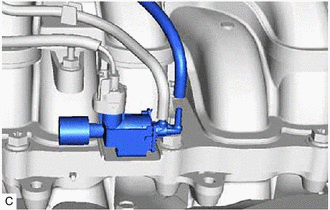
| 5. | INSPECT NO. 1 VACUUM SWITCHING VALVE (FOR INTAKE AIR CONTROL VALVE SUB-ASSEMBLY) |
(a) Inspect the No. 1 vacuum switching valve (for intake air control valve sub-assembly).
Click here
| NG | | REPLACE NO. 1 VACUUM SWITCHING VALVE (FOR INTAKE AIR CONTROL VALVE SUB-ASSEMBLY) |
|
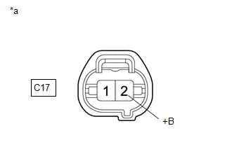
| 6. | CHECK TERMINAL VOLTAGE (POWER SOURCE OF NO. 1 VACUUM SWITCHING VALVE (FOR INTAKE AIR CONTROL VALVE SUB-ASSEMBLY)) |
| (a) Disconnect the No. 1 vacuum switching valve (for intake air control valve sub-assembly) connector. |
|
(b) Turn the engine switch on (IG).
(c) Measure the voltage according to the value(s) in the table below.
Standard Voltage:
| Tester Connection | Condition | Specified Condition |
|---|---|---|
| C17-2 (+B) - Body ground | Engine switch on (IG) | 11 to 14 V |
| NG | | GO TO STEP 8 |
|
| 7. | CHECK HARNESS AND CONNECTOR (NO. 1 VACUUM SWITCHING VALVE (FOR INTAKE AIR CONTROL VALVE SUB-ASSEMBLY) - ECM) |
(a) Disconnect the No. 1 vacuum switching valve (for intake air control valve sub-assembly) connector.
(b) Disconnect the ECM connector.
(c) Measure the resistance according to the value(s) in the table below.
Standard Resistance:
| Tester Connection | Condition | Specified Condition |
|---|---|---|
| C17-1 (ACIS) - C32-66 (ACIS) | Always | Below 1 Ω |
| C17-1 (ACIS) or C32-66 (ACIS) - Body ground and other terminals | Always | 10 kΩ or higher |
| OK | | REPLACE ECM |
| NG | | REPAIR OR REPLACE HARNESS OR CONNECTOR |
| 8. | CHECK HARNESS AND CONNECTOR (EFI-MAIN NO. 1 RELAY - NO. 1 VACUUM SWITCHING VALVE (FOR INTAKE AIR CONTROL VALVE SUB-ASSEMBLY)) |
(a) Remove the EFI-MAIN NO. 1 relay from the No. 1 engine room relay block and No. 1 junction block assembly.
(b) Disconnect the No. 1 vacuum switching valve (for intake air control valve sub-assembly) connector.
(c) Measure the resistance according to the value(s) in the table below.
Standard Resistance:
| Tester Connection | Condition | Specified Condition |
|---|---|---|
| 5 (EFI-MAIN NO. 1 relay) - C17-2 (+B) | Always | Below 1 Ω |
| 5 (EFI-MAIN NO. 1 relay) or C17-2 (+B) - Body ground and other terminals | Always | 10 kΩ or higher |
| OK | | GO TO ECM POWER SOURCE CIRCUIT |
| NG | | REPAIR OR REPLACE HARNESS OR CONNECTOR |
| 9. | INSPECT VACUUM PUMP ASSEMBLY |
(a) Inspect the vacuum pump assembly.
-
for TMC Made: Click here
-
for TMMK Made: Click here
| OK | | REPAIR OR REPLACE VACUUM HOSE SUB-ASSEMBLY (NO. 1 VACUUM SWITCHING VALVE (FOR INTAKE AIR CONTROL VALVE SUB-ASSEMBLY) - VACUUM PUMP ASSEMBLY) |
| NG | | REPLACE VACUUM PUMP ASSEMBLY |
READ NEXT:
 Brake Override System
DESCRIPTION When the vehicle is being driven, depressing the accelerator pedal sensor assembly and brake pedal will activate the brake override system to restrict engine output. The conditions for act
MIL Circuit
DESCRIPTION The Malfunction Indicator Lamp (MIL) is used to indicate vehicle malfunctions detected by the ECM. The MIL operation can be checked visually. When the engine switch is first turned on (IG)
Drive Start Control
DESCRIPTION The drive start control is controlled by the ECM. If the ECM determines that the shift lever and accelerator pedal are operated abnormally, engine output is restricted and, when necessary,
SEE MORE:
Hydraulic Test
HYDRAULIC TEST PERFORM HYDRAULIC TEST CAUTION:
Do not perform a stall test if there are any people or objects near the vehicle.
The vehicle could begin moving suddenly, resulting in a serious accident.
Do not perform a stall test if any wheel chocks are out of position.
The vehicle co
On-vehicle Inspection
ON-VEHICLE INSPECTION PROCEDURE 1. INSPECT BRAKE BOOSTER ASSEMBLY (a) Airtightness check (1) Start the engine and stop it after 1 or 2 minutes. Slowly depress the brake pedal several times. HINT: If the brake pedal can be depressed nearly to the floor the first time, but on the 2nd and 3rd time c
