Lexus ES: Windshield Deicer does not Operate
DESCRIPTION
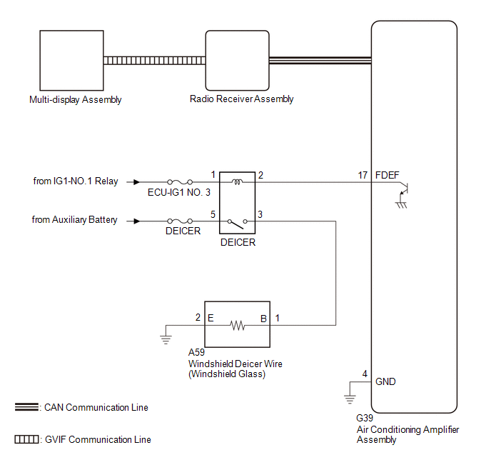
When the front wiper deicer switch is operated, the operation signal is transmitted to the air conditioning amplifier assembly directly. When the air conditioning amplifier assembly receives the signal, it turns on the DEICER relay to operate the windshield deicer system.
WIRING DIAGRAM
CAUTION / NOTICE / HINT
NOTICE:
- Inspect the fuses for circuits related to this system before performing the following procedure.
- If the auxiliary battery voltage becomes low, auxiliary battery load control will operate in order to ensure sufficient power is supplied to the power steering system. In this case, the windshield deicer system may not operate.
-
The windshield deicer system uses the CAN communication system. First, confirm that there are no malfunctions in the CAN communication system. Refer to How to Proceed with Troubleshooting.
Click here
.gif)
PROCEDURE
| 1. | CHECK AIR CONDITIONING SYSTEM |
(a) Check that the air conditioning system can be operated using the remote touch.
HINT:
Both the windshield deicer system operation signal and airconditioning system operation signal are transmitted to the airconditioning amplifier assembly through same communication line.
OK:
The air conditioning system operates normally.
| NG | .gif) | GO TO AIR CONDITIONING SYSTEM |
|
.gif)
| 2. | PERFORM ACTIVE TEST USING TECHSTREAM |
(a) Connect the Techstream to the DLC3.
(b) Turn the power switch on (IG).
(c) Turn the Techstream on.
(d) Enter the following menus: Body Electrical / Air Conditioner / Active Test.
(e) Perform the Active Test according to the display on the Techstream.
Body Electrical > Air Conditioner > Active Test| Tester Display | Measurement Item | Control Range | Diagnostic Note |
|---|---|---|---|
| Deicer Relay (Front) | Windshield deicer wire (windshield glass) | OFF or ON | - |
| Tester Display |
|---|
| Deicer Relay (Front) |
OK:
The windshield deicer system operates normally.
| NG | | GO TO STEP 5 |
|
| 3. | REPLACE AIR CONDITIONING AMPLIFIER ASSEMBLY |
(a) Replace the air conditioning amplifier assembly with a new or known good one.
Click here
(b) Check that the windshield deicer system operates normally.
OK:
The windshield deicer system operates normally.
| OK | | END (AIR CONDITIONING AMPLIFIER ASSEMBLY WAS DEFECTIVE) |
|
| 4. | REPLACE RADIO RECEIVER ASSEMBLY |
(a) Replace the radio receiver assembly with a new or known good one.
Click here
(b) Check that the windshield deicer system operates normally.
OK:
The windshield deicer system operates normally.
| OK | | END (RADIO RECEIVER ASSEMBLY WAS DEFECTIVE) |
| NG | | REPLACE MULTI-DISPLAY ASSEMBLY |
| 5. | INSPECT DEICER RELAY |
(a) Inspect the DEICER relay.
Click here
| NG | | REPAIR OR REPLACE HARNESS OR CONNECTOR |
|
| 6. | CHECK WIRE HARNESS AND CONNECTOR (DEICER RELAY - IG POWER SUPPLY) |
| (a) Measure the voltage according to the value(s) in the table below. Standard Voltage:
|
|
.png)
| NG | | REPAIR OR REPLACE HARNESS OR CONNECTOR |
|
| 7. | CHECK WIRE HARNESS AND CONNECTOR (DEICER RELAY - AIR CONDITIONING AMPLIFIER ASSEMBLY) |
| (a) Disconnect G39 air conditioning amplifier assembly connector. |
|
(b) Measure the resistance according to the value(s) in the table below.
Standard Resistance:
| Tester Connection | Condition | Specified Condition |
|---|---|---|
| DEICER relay holder terminal 2 - G39-17 (FDEF) | Always | Below 1 Ω |
| DEICER relay holder terminal 2 - Body ground | Always | 10 kΩ higher |
| NG | | REPAIR OR REPLACE HARNESS OR CONNECTOR |
|
| 8. | CHECK AIR CONDITIONING AMPLIFIER ASSEMBLY |
(a) Reconnect the G39 air conditioning amplifier assembly connector.
| (b) Measure the voltage according to the value(s) in the table below. Standard Voltage:
|
|
.png)
| NG | | REPLACE AIR CONDITIONING AMPLIFIER ASSEMBLY |
|
| 9. | CHECK WIRE HARNESS AND CONNECTOR (DEICER RELAY - WINDSHIELD DEICER WIRE (WINDSHIELD GLASS)) |
| (a) Disconnect A59 windshield deicer wire (windshield glass) connector. |
|
.png)
(b) Measure the resistance according to the value(s) in the table below.
Standard Resistance:
| Tester Connection | Condition | Specified Condition |
|---|---|---|
| DEICER relay holder terminal 3 - A59-1 (B) | Always | Below 1 Ω |
| DEICER relay holder terminal 3 - Body ground | Always | 10 kΩ higher |
| NG | | REPAIR OR REPLACE HARNESS OR CONNECTOR |
|
| 10. | CHECK WIRE HARNESS AND CONNECTOR (WINDSHIELD DEICER WIRE (WINDSHIELD GLASS) - BODY GROUND) |
(a) Measure the resistance according to the value(s) in the table below.
Standard Resistance:
| Tester Connection | Condition | Specified Condition |
|---|---|---|
| A59-2 (E) - Body ground | Always | Below 1 Ω |
| OK | | REPLACE WINDSHIELD DEICER WIRE (WINDSHIELD GLASS) |
| NG | | REPAIR OR REPLACE HARNESS OR CONNECTOR |
READ NEXT:
 Components
COMPONENTS ILLUSTRATION *1 COWL TOP VENTILATOR LOUVER SUB-ASSEMBLY *2 FRONT WIPER ARM AND BLADE ASSEMBLY LH *3 FRONT WIPER ARM AND BLADE ASSEMBLY RH *4 FRONT WIPER ARM HEAD CAP
Removal
REMOVAL CAUTION / NOTICE / HINT The necessary procedures (adjustment, calibration, initialization or registration) that must be performed after parts are removed and installed, or replaced during wind
SEE MORE:
Initialization
INITIALIZATION INITIALIZE SLIDING ROOF SYSTEM NOTICE:
When the sliding roof glass sub-assembly or sliding roof drive cable sub-assembly is adjusted or removed/installed, or the sliding roof drive gear sub-assembly is replaced, the sliding roof ECU (sliding roof drive gear sub-assembly) must be in
Motor Generator ECU(EEPROM) Calibration / Parameter Memory Failure (P1C2E46)
DESCRIPTION The motor generator control ECU monitors its internal operation and will store this DTC if it detects a malfunction in its EEPROM. DTC No. Detection Item DTC Detection Condition Trouble Area MIL Warning Indicate P1C2E46 Motor Generator ECU(EEPROM) Calibration / Paramet
