Lexus ES: Vehicle Speed Signal Circuit between Stereo Component Amplifier and Combination Meter
DESCRIPTION
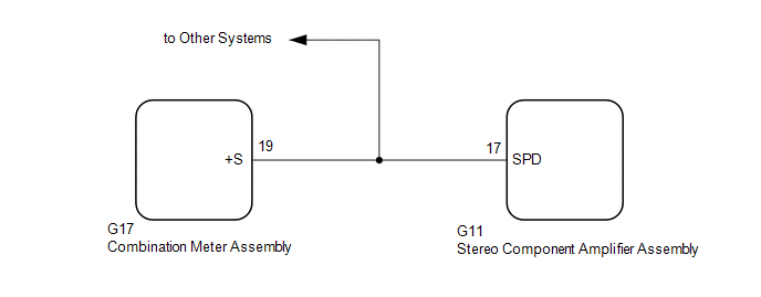
The stereo component amplifier assembly receives a vehicle speed signal from the combination meter assembly to control the ASL function.
HINT:
- A voltage of 12 V or 5 V is output from each ECU and then input to the combination meter assembly. The signal is changed to a pulse signal at the transistor in the combination meter assembly. Each ECU controls its respective systems based on this pulse signal.
- If a short occurs in any of the ECUs or in the wire harness connected to an ECU, all systems in the following diagram will not operate normally.
WIRING DIAGRAM
PROCEDURE
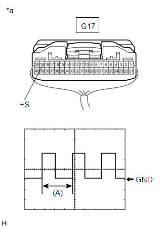
| 1. | INSPECT COMBINATION METER ASSEMBLY (OUTPUT WAVEFORM) |
| (a) Check the output waveform. (1) Remove the combination meter assembly with the connector(s) still connected. (2) Connect an oscilloscope to terminal G17-19 (+S) and body ground. (3) Turn the power switch on (IG). (4) Turn a wheel slowly. (5) Check the signal waveform according to the condition(s) in the table below.
OK: The waveform is similar to that shown in the illustration. HINT: When the system is functioning normally, one wheel revolution generates 4 pulses. As the vehicle speed increases, the width indicated by (A) in the illustration narrows. |
|
| NG |  | GO TO METER / GAUGE SYSTEM |
|

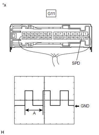
| 2. | INSPECT STEREO COMPONENT AMPLIFIER ASSEMBLY (INPUT WAVEFORM) |
| (a) Check the input waveform. (1) Remove the stereo component amplifier assembly with the connector(s) still connected. (2) Connect an oscilloscope to terminal G11-17 (SPD) and body ground. (3) Turn the power switch on (IG). (4) Turn a wheel slowly. (5) Check the signal waveform according to the condition(s) in the table below.
OK: The waveform is similar to that shown in the illustration. HINT: When the system is functioning normally, one wheel revolution generates 4 pulses. As the vehicle speed increases, the width indicated by (A) in the illustration narrows. |
|
| OK | | PROCEED TO NEXT SUSPECTED AREA SHOWN IN PROBLEM SYMPTOMS TABLE |
.gif)
| NG | | REPAIR OR REPLACE HARNESS OR CONNECTOR |
READ NEXT:
 Visual Mute Signal Circuit between Radio Receiver and Multi-display
DESCRIPTION The radio receiver assembly sends a visual mute signal to the multi-display assembly. As a result, a black screen is displayed when the screen changes so that noise and distorted images ar
Voice Guidance does not Function
WIRING DIAGRAM PROCEDURE 1. CHECK VOICE GUIDANCE SETTING (a) Check that the voice guidance settings are not off. OK: Voice guidance settings are not off. NG CHANGE VOICE GUIDANCE SETT
Voice is not Recognized
PROCEDURE 1. CHECK CONDITION (a) While paying attention to the condition of the spoken voice command, perform a voice recognition operation. OK: Voice command is recognized normally. HINT:
SEE MORE:
DC/DC Converter Current Sensor Circuit Current Out of Range (P31531D)
DTC SUMMARY MALFUNCTION DESCRIPTION This DTC is stored if the value of the reactor current sensor fluctuates excessively. The cause of this malfunction may be one of the following: Area Main Malfunction Description Hybrid vehicle transaxle assembly
Open or short circuit in the motor or
Freeze Frame Data
FREEZE FRAME DATA FREEZE FRAME DATA HINT: The hybrid vehicle control ECU records vehicle and driving condition information as freeze frame data the moment a DTC is stored. It can be used for estimating or duplicating the vehicle conditions that were present when the malfunction occurred. (a) Connect
