
Lexus ES: Components
COMPONENTS
ILLUSTRATION
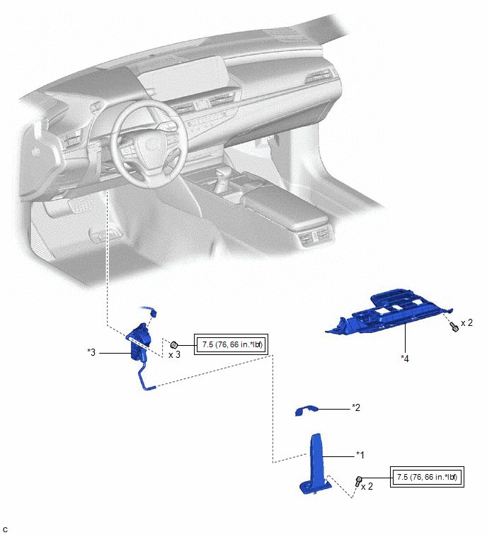
| *1 | ACCELERATOR PEDAL ASSEMBLY | *2 | ACCELERATOR PEDAL PAD |
| *3 | ACCELERATOR PEDAL SENSOR ASSEMBLY | *4 | NO. 1 INSTRUMENT PANEL UNDER COVER SUB-ASSEMBLY |
.png) | Tightening torque for "Major areas involving basic vehicle performance such as moving/turning/stopping": N*m (kgf*cm, ft.*lbf) | - | - |
READ NEXT:
 On-vehicle Inspection
ON-VEHICLE INSPECTION PROCEDURE 1. INSPECT ACCELERATOR PEDAL(W/SENSOR) ROD ASSEMBLY (a) Connect the Techstream to the DLC3. (b) Turn the engine switch on (IG). (c) Turn the Techstream on. (d) Enter th
Removal
REMOVAL PROCEDURE 1. REMOVE NO. 1 INSTRUMENT PANEL UNDER COVER SUB-ASSEMBLY Click here 2. REMOVE ACCELERATOR PEDAL(W/SENSOR) ROD ASSEMBLY NOTICE:
Avoid physical shock to the accelerator pedal se
Installation
INSTALLATION PROCEDURE 1. INSTALL ACCELERATOR PEDAL ASSEMBLY (a) Engage the claw to install the accelerator pedal assembly. (b) Install the 2 bolts. Torque: 7.5 N·m {76 kgf·cm, 66 in
SEE MORE:
Distance Control Switch Circuit
DESCRIPTION The vehicle-to-vehicle distance control switch is used to set the distance for vehicle-to-vehicle distance control mode. The vehicle-to-vehicle distance control switch is installed in the steering pad switch assembly. The vehicle-to-vehicle distance set value can be changed by operating
Installation
INSTALLATION CAUTION / NOTICE / HINT NOTICE: This procedure includes the installation of small-head bolts. Refer to Small-Head Bolts of Basic Repair Hint to identify the small-head bolts. Click here PROCEDURE 1. INSTALL FUEL PRESSURE SENSOR HINT: Perform "Inspection After Repair" after replacing t
© 2016-2026 Copyright www.lexguide.net
