Lexus ES: UART Communication Between ANC and Audio Amplifier Missing Message (B1AA187)
DESCRIPTION
This DTC is stored when an UART communication error occurs between the stereo component equalizer assembly and stereo component amplifier assembly.
| DTC No. | Detection Item | DTC Detection Condition | Trouble Area |
|---|---|---|---|
| B1AA187 | UART Communication Between ANC and Audio Amplifier Missing Message | Stereo component equalizer assembly detects a UART communication malfunction in stereo component amplifier assembly for 4 seconds or more continuously* |
|
HINT:
*: Malfunction monitoring is not performed under the following conditions, in order to prevent erroneous detection.
- After power switch is turned on (ACC) for 3 seconds or more.
- After the auxiliary battery voltage returns to normal for 3 seconds.
- Before 3 seconds have elapsed after auxiliary battery voltage has returned to normal.
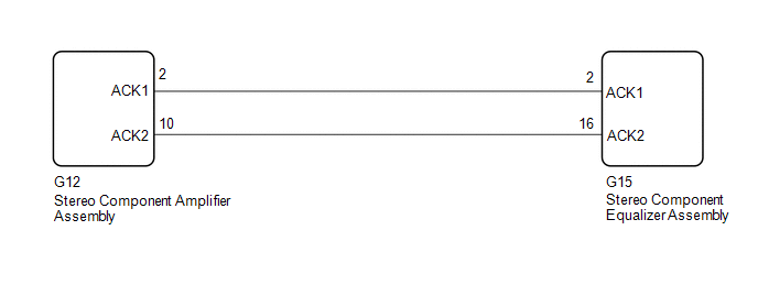
WIRING DIAGRAM
PROCEDURE
| 1. | CLEAR DTC |
(a) Clear the DTCs.
Body Electrical > Active Noise Control > Clear DTCs
|

| 2. | CHECK FOR DTC |
(a) Check for DTCs with all of the detection conditions met.
Body Electrical > Active Noise Control > Trouble CodesOK:
No DTCs are output.
| OK |  | USE SIMULATION METHOD TO CHECK |
|
| 3. | CHECK HARNESS AND CONNECTOR (STEREO COMPONENT EQUALIZER ASSEMBLY - STEREO COMPONENT AMPLIFIER ASSEMBLY) |
(a) Disconnect the G15 stereo component equalizer assembly connector.
(b) Disconnect the G12 stereo component amplifier assembly connector.
(c) Measure the resistance according to the value(s) in the table below.
Standard Resistance:
| Tester Connection | Condition | Specified Condition |
|---|---|---|
| G15-2 (ACK1) - G12-2 (ACK1) | Always | Below 1 Ω |
| G15-16 (ACK2) - G12-10 (ACK2) | Always | Below 1 Ω |
| G15-2 (ACK1) or G12-2 (ACK1) - Body ground | Always | 10 kΩ or higher |
| G15-16 (ACK2) or G12-10 (ACK2) - Body ground | Always | 10 kΩ or higher |
| NG | | REPAIR OR REPLACE HARNESS OR CONNECTOR |
|
| 4. | REPLACE STEREO COMPONENT AMPLIFIER ASSEMBLY |
(a) Replace the stereo component amplifier assembly with a new or known good one.
Click here .gif)
|
| 5. | CLEAR DTC |
(a) Clear the DTCs.
Body Electrical > Active Noise Control > Clear DTCs
|
| 6. | CHECK FOR DTC |
(a) Check for DTCs with all of the detection conditions met.
Body Electrical > Active Noise Control > Trouble CodesOK:
No DTCs are output.
| OK | | END (STEREO COMPONENT AMPLIFIER ASSEMBLY IS DEFECTIVE) |
| NG | | REPLACE STEREO COMPONENT EQUALIZER ASSEMBLY |
READ NEXT:
 Front Left Microphone Circuit Component Internal Failure (B1AA296,B1AA31C)
DESCRIPTION These DTCs are stored when a malfunction occurs in the No. 1 active noise control microphone system. DTC No. Detection Item DTC Detection Condition Trouble Area B1AA296 Fron
Front Right Microphone Circuit Component Internal Failure (B1AA696,B1AA71C)
DESCRIPTION These DTCs are stored when a malfunction occurs in the No. 2 active noise control microphone system. DTC No. Detection Item DTC Detection Condition Trouble Area B1AA696 Fron
Rear Center Microphone Circuit Component Internal Failure (B1AAA96,B1AAB1C)
DESCRIPTION These DTCs are stored when a malfunction occurs in the No. 3 active noise control microphone system. DTC No. Detection Item DTC Detection Condition Trouble Area B1AAA96 Rear
SEE MORE:
Pressure Control Solenoid "L" Actuator Stuck Off (P08BA7F)
DESCRIPTION Based on signals from the transmission revolution sensors (NT and NC), the actual gear is detected. The ECM compares the actual gear with the shift schedule in the ECM memory to detect mechanical malfunctions of the solenoid valves, transmission valve body assembly and automatic transaxl
Fuel Pump (for High Pressure)
ComponentsCOMPONENTS ILLUSTRATION *1 NO. 1 FUEL PIPE SUB-ASSEMBLY *2 FUEL PUMP ASSEMBLY *3 FUEL TUBE SUB-ASSEMBLY *4 FUEL PUMP LIFTER ASSEMBLY *5 FUEL PUMP FLANGE *6 FUEL PUMP SPACER GASKET *7 O-RING *8 FUEL PUMP PROTECTOR Tightening torque for "Major
