Lexus ES: Torque Converter Clutch Pressure Control Solenoid Control Actuator Stuck Off (P27567F)
DESCRIPTION
The ECM controls the solenoid (SLU) valve using a predetermined current, and performs lock-up and flex lock-up control.
The ECM compares the engagement condition of the lock-up clutch with the lock-up schedule in the ECM memory to detect mechanical malfunctions of the solenoid (SLU) valve, transmission valve body assembly and torque converter assembly.
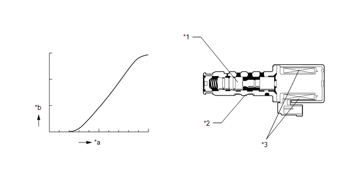
| *1 | Spool Valve | *2 | Sleeve |
| *3 | Solenoid Coil | - | - |
| *a | Current | *b | Hydraulic Pressure |
| DTC No. | Detection Item | DTC Detection Condition | Trouble Area | MIL | Memory | Note |
|---|---|---|---|---|---|---|
| P27567F | Torque Converter Clutch Pressure Control Solenoid Control Actuator Stuck Off | All of the following conditions are met (2-trip detection logic):
|
| Comes on | DTC stored | SAE Code: P2757 |
| Vehicle Condition | |||
|---|---|---|---|
| Pattern 1 | Pattern 2 | ||
| Diagnostic Condition | Engine coolant temperature is 40°C (104°F) or higher. | ○ | ○ |
| ATF temperature is -10°C (14°F) or higher. | ○ | ○ | |
| The vehicle is being driven with the shift lever in D. | ○ | ○ | |
| No malfunctions are detected in the solenoid (SL1, SL2, SL3, SL4, SL5, SL6, SL, SLU and SLT) valves, transmission revolution sensors (NT and NC), coolant temperature sensor, oil temperature sensor, knock sensor, crankshaft position sensor circuits, electronic throttle or CAN communication system. | ○ | ○ | |
| Malfunction Condition | When the ECM sends a lock-up OFF request, the difference between the input turbine speed (NT) and the engine speed (NE) is less than 35 rpm. | ○ | - |
| When the ECM sends a lock-up ON request, the difference between the input turbine speed (NT) and the engine speed (NE) is 170 rpm or more. | - | ○ | |
| Duration | 1.8 seconds or more | 3.5 seconds or more | |
| Detection Logic | 2-trip detection logic | 2-trip detection logic | |
HINT:
This DTC is stored when either of the above detection patterns is met.
MONITOR DESCRIPTION
Torque converter lock-up is controlled by the ECM based on the transmission revolution sensor (NT and NC), engine speed, engine load, engine temperature, vehicle speed, ATF temperature and gear selection signals. The ECM determines the lock-up status of the torque converter assembly by comparing the engine speed (NE) to the transmission revolution sensor (NT) signal. The ECM calculates the actual gear by comparing the transmission revolution sensor (NT) signal to the transmission revolution sensor (NC) signal. When conditions are appropriate, the ECM requests "lock-up" by applying voltage to the solenoid (SLU) valve. When the solenoid (SLU) valve is turned on, pressure is applied to the lock-up relay valve and locks the torque converter assembly.
If the ECM does not detect lock-up after lock-up has been requested or if it detects lock-up when it is not requested, it interprets this as a malfunction of the solenoid (SLU) valve, illuminates the MIL and stores this DTC.
HINT:
Example:
When any of the following is met, the system judges it as a malfunction.
- There is a difference in speed between the input side (engine speed) and output side (input turbine speed) of the torque converter assembly when the ECM commands lock-up. (Engine speed is at least 170 rpm more than input turbine speed.)
- There is no difference in speed between the input side (engine speed) and output side (input turbine speed) of the torque converter assembly when the ECM commands lock-up off. (The difference between engine speed and input turbine speed is less than 35 rpm.)
MONITOR STRATEGY
| Related DTCs | P2757: Solenoid (SLU) valve/OFF malfunction Solenoid (SLU) valve/ON malfunction |
| Required sensors/components | Solenoid (SLU) valve |
| Frequency of operation | Continuous |
| Duration | OFF malfunction: 3.5 sec. ON malfunction (A): 1.8 sec. ON malfunction (B): 0.5 sec. ON malfunction (C): - |
| MIL operation | 2 driving cycles |
| Sequence of operation | None |
TYPICAL ENABLING CONDITIONS
All| The monitor will run whenever the following DTCs are not stored | P0717, P07BF, P07C0 (Turbine speed sensor circuit) P0793, P07C5, P07C6 (Intermediate shaft speed sensor circuit) P0962, P0963 (Solenoid (SL1) valve circuit) P0966, P0967 (Solenoid (SL2) valve circuit) P0970, P0971 (Solenoid (SL3) valve circuit) P2814, P2815 (Solenoid (SL4) valve circuit) P281D, P281E (Solenoid (SL5) valve circuit) P08C1, P08C2 (Solenoid (SL6) valve circuit) P2763, P2764 (Solenoid (SLU) valve circuit) P2769, P2770 (Solenoid (SL) valve circuit) P2720, P2721 (Solenoid (SLT) valve circuit) P0712, P0713 (ATF temperature sensor circuit (TFT sensor)) P0117, P0118 (ECT sensor circuit) P0335, P0337, P0338 (Crankshaft position sensor circuit) P0327, P0328, P0332, P0333 (KCS sensor circuit) P0121, P0122, P0123, P0222, P0223, P0604, P0606, P060A, P060B, P060D, P060E, P061E, P0657, P0658, P2102, P2103, P2111, P2112, P2119, P2135 ((ETCS) Electronic throttle control system) U0100 (CAN communication system) |
| Shift position | "D", "not R" and "not N" |
| Elapsed time since shift lever moved from "N" to "D" | 4 sec. or more |
| ATF temperature | -10°C (14°F) or more |
| Engine | Starting |
| Fail-safe function does not operate due to the following malfunctions: | - |
| Solenoid (SLT) valve | ON malfunction (P2714) |
| Solenoid (SLU) valve | OFF or ON malfunction (P2757) |
| Solenoid (SL) valve | ON malfunction (P0741) |
| ECT | 40°C (104°F) or more |
| Spark advance from MAX. retard timing by KCS control | 0 °CA or more |
| ECM selected gear | Actual gear |
| Vehicle speed | 10 km/h (6.2 mph) or more |
| ECM commanded solenoid (SL) valve state | OFF |
| ECM commanded pressure value using solenoid (SLU) valve (3 sec. or more) | - |
| - when A/C off | 444 kPa (4.5 kgf/cm2, 64 psi) or more |
| - when A/C on | 444 kPa (4.5 kgf/cm2, 64 psi) or more |
| Fail-safe function does not operate due to the following malfunctions: | - |
| Solenoid (SLT) valve | ON malfunction (P2714) |
| Solenoid (SLU) valve | OFF or ON malfunction (P2757) |
| Solenoid (SL) valve | ON malfunction (P0741) |
| ECT | 40°C (104°F) or more |
| Spark advance from MAX. retard timing by KCS control | 0 °CA or more |
| ECM selected gear | Actual gear |
| Vehicle speed | 10 km/h (6.2 mph) or more and less than 60 km/h (37.3 mph) |
| Quick engagement detection | Fixed |
| ECM commanded pressure value using solenoid (SLU) valve | 0 kPa (0 kgf/cm2, 0 psi) or less |
| Time since ECM commanded solenoid (SL) valve OFF | 0.15 sec. or more |
| Throttle valve opening angle | 6% or more at turbine speed 2000 rpm (Conditions vary with turbine speed) |
| Calculated load value | - |
| - when A/C off | 16% or more at turbine speed 2000 rpm (Conditions vary with turbine speed) |
| - when A/C on | 21% or more at turbine speed 2000 rpm (Conditions vary with turbine speed) |
| Calculated input torque | 0 N*m (0 kgf*cm, 0 ft.*lbf) or more |
| Fail-safe function does not operate due to the following malfunctions: | - |
| Solenoid (SL1) valve | OFF or ON malfunction (P0746) |
| Solenoid (SL2) valve | OFF or ON malfunction (P0776) |
| Solenoid (SL3) valve | OFF or ON malfunction (P0796) |
| Solenoid (SL4) valve | OFF or ON malfunction (P2808) |
| Solenoid (SL5) valve | OFF or ON malfunction (P2817) |
| Solenoid (SL6) valve | OFF or ON malfunction (P08BB) |
| Solenoid (SLT) valve | OFF malfunction (P2714) |
| Solenoid (SLU) valve | ON malfunction (P2757) |
| Solenoid (SL) valve | ON malfunction (P0741) |
| All shift solenoid | Not being stopped |
| Neutral command flag | Not met |
| Vehicle stop check | Fixed |
| ECM selected gear | 3rd, 4th, 6th or 7th |
| ECM selected gear | 3rd, 4th, 6th or 7th |
HINT:
Actual gear:- 1st gear
2nd gearAny of the following conditions are met
(a) or (b)
(a) Turbine speed/Output speed (NT/NO)
4.454 or more and 9.051 or less
(When output speed less than 60 rpm)
(b) NT-NO x 1st gear ratio
-50 rpm or more and 50 rpm or less
(When output speed 60 rpm or more)
3rd gearAny of the following conditions are met
(a) or (b)
(a) Turbine speed/Output speed (NT/NO)
2.758 or more and 3.297 or less
(When output speed less than 190 rpm)
(b) NT-NO x 2nd gear ratio
-50 rpm or more and 50 rpm or less
(When output speed 190 rpm or more)
4th gearAny of the following conditions are met
(a) or (b)
(a) Turbine speed/Output speed (NT/NO)
1.817 or more and 2.082 or less
(When output speed less than 380 rpm)
(b) NT-NO x 3rd gear ratio
-50 rpm or more and 50 rpm or less
(When output speed 380 rpm or more)
5th gearAny of the following conditions are met
(a) or (b)
(a) Turbine speed/Output speed (NT/NO)
1.368 or more and 1.544 or less
(When output speed less than 570 rpm)
(b) NT-NO x 4th gear ratio
-50 rpm or more and 50 rpm or less
(When output speed 570 rpm or more)
6th gearAny of the following conditions are met
(a) or (b)
(a) Turbine speed/Output speed (NT/NO)
1.129 or more and 1.308 or less
(When output speed less than 570 rpm)
(b) NT-NO x 5th gear ratio
-50 rpm or more and 50 rpm or less
(When output speed 570 rpm or more)
7th gearAny of the following conditions are met
(a) or (b)
(a) Turbine speed/Output speed (NT/NO)
0.934 or more and 1.065 or less
(When output speed less than 770 rpm)
(b) NT-NO x 6th gear ratio
-50 rpm or more and 50 rpm or less
(When output speed 770 rpm or more)
8th gearAny of the following conditions are met
(a) or (b)
(a) Turbine speed/Output speed (NT/NO)
0.744 or more and 0.876 or less
(When output speed less than 780 rpm)
(b) NT-NO x 7th gear ratio
-50 rpm or more and 50 rpm or less
(When output speed 780 rpm or more)
Any of the following conditions are met
(a) or (b)
(a) Turbine speed/Output speed (NT/NO)
0.621 or more and 0.725 or less
(When output speed less than 960 rpm)
(b) NT-NO x 8th gear ratio
-50 rpm or more and 50 rpm or less
(When output speed 960 rpm or more)
| l Engine speed - Turbine speed l | Less than 50 rpm |
| Time since ECM commanded solenoid (SL) valve OFF | Less than 0.28 sec. |
| Vehicle speed | 0 km/h (0 mph) or less |
| Turbine speed - output speed x (ECM selected gear ratio) | 1000 rpm or more |
| Engine speed | 7200 rpm or more |
| Turbine speed | 7200 rpm or more |
-
Any of the following conditions are met: Condition (a) or (b)
-
Condition (a)
ECM selected gear
6th or 7th or 8th
Output speed x 5th gear ratio
7200 rpm or more
Condition (b)
ECM selected gear
4th or 5th
Output speed x 3rd gear ratio
7200 rpm or more
-
Condition (a)
TYPICAL MALFUNCTION THRESHOLDS
OFF malfunction| Engine speed - Turbine speed | 170 rpm or more |
-
Any of the following conditions are met: ON malfunction (A), (B) or (C) ON malfunction (A)
ON malfunction (B)l Engine speed - Turbine speed l
Less than 35 rpm
ON malfunction (C)Neutral state flag
ON
Solenoid (SLT) valve
ON malfunction
| Turbine speed - output speed x (ECM selected gear ratio) | 1000 rpm or more |
CONFIRMATION DRIVING PATTERN
CAUTION:
When performing the confirmation driving pattern, obey all speed limits and traffic laws.
HINT:
- After repairs have been completed, clear the DTCs and then check that the vehicle has returned to normal by performing the following All Readiness check procedure.
-
When clearing the permanent DTCs, refer to the Clear Permanent DTC procedure.
Click here
.gif)
- Connect the Techstream to the DLC3.
- Turn the engine switch on (IG) and turn the Techstream on.
- Clear the DTCs (even if no DTCs are stored, perform the clear DTC procedure).
- Turn the engine switch off and wait for 2 minutes or more.
- Turn the engine switch on (IG) and turn the Techstream on.
- Start the engine.
-
Perform the Lock-up Function inspection in Road Test. [*1]
Click here
HINT:
[*1] : Normal judgment procedure.
The normal judgment procedure is used to complete DTC judgment and also used when clearing permanent DTCs.
- Stop the vehicle.
- Enter the following menus: Powertrain / Transmission / Utility / All Readiness.
- Input the DTC: P27567F.
-
Check the DTC judgment result.
Techstream Display
Description
NORMAL
- DTC judgment completed
- System normal
ABNORMAL
- DTC judgment completed
- System abnormal
INCOMPLETE
- DTC judgment not completed
- Perform driving pattern after confirming DTC enabling conditions
N/A
- Unable to perform DTC judgment
- Number of DTCs which do not fulfill DTC preconditions has reached ECU memory limit
HINT:
- If the judgment result shows NORMAL, the system is normal.
- If the judgment result shows ABNORMAL, the system has a malfunction.
- If the judgment result shows INCOMPLETE or N/A, perform the normal judgment procedure again.
CAUTION / NOTICE / HINT
NOTICE:
-
Perform the universal trip to clear permanent DTCs.
Click here
-
Perform registration and/or initialization when parts related to the automatic transaxle are replaced.
Click here
PROCEDURE
| 1. | CHECK DTC OUTPUT (IN ADDITION TO DTC P27567F) |
(a) Connect the Techstream to the DLC3.
(b) Turn the engine switch on (IG).
(c) Turn the Techstream on.
(d) Enter the following menus: Powertrain / Transmission / Trouble Codes.
Powertrain > Transmission > Trouble Codes(e) Read the DTCs using the Techstream.
| Result | Proceed to |
|---|---|
| Only DTC P27567F is output | A |
| DTC P27567F and other DTCs are output | B |
HINT:
- If any DTCs other than P27567F are output, perform troubleshooting for those DTCs first.
- If a solenoid valve is stuck ON or OFF, DTCs for several solenoid valves including the malfunctioning solenoid valve will be stored.
| B | .gif) | GO TO DTC CHART |
|
.gif)
| 2. | INSPECT SOLENOID (SLU) VALVE |
| (a) Remove the solenoid (SLU) valve. Click here |
|
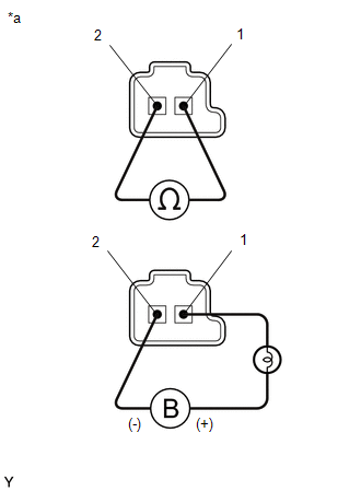
(b) Measure the resistance according to the value(s) in the table below.
Standard Resistance:
| Tester Connection | Condition | Specified Condition |
|---|---|---|
| Solenoid (SLU) valve connector terminal 1 - Terminal 2 | 20°C (68°F) | 5.0 to 5.6 Ω |
(c) Connect a positive (+) lead from the battery with a 21 W bulb to terminal 1 and a negative (-) lead to terminal 2 of the solenoid valve connector. Check that the valve moves and makes an operating sound.
OK:
Valve moves and makes an operating sound.
| NG | | REPLACE SOLENOID (SLU) VALVE |
|
| 3. | INSPECT TRANSMISSION VALVE BODY ASSEMBLY |
(a) Inspect the transmission valve body assembly.
Click here
OK:
There is no foreign matter on each valve and they operate smoothly.
| NG | | REPAIR OR REPLACE TRANSMISSION VALVE BODY ASSEMBLY |
|
| 4. | INSPECT TORQUE CONVERTER ASSEMBLY |
(a) Inspect the torque converter assembly.
Click here
OK:
The torque converter assembly is normal.
| NG | | REPAIR OR REPLACE TORQUE CONVERTER ASSEMBLY |
|
| 5. | REPAIR OR REPLACE AUTOMATIC TRANSAXLE ASSEMBLY |
(a) Repair or replace the automatic transaxle assembly.
Click here
| NEXT | | PERFORM REGISTRATION |
READ NEXT:
 Pressure Control Solenoid "G" Actuator Stuck Off (P28077F)
DESCRIPTION Based on signals from the transmission revolution sensors (NT and NC), the actual gear is detected. The ECM compares the actual gear with the shift schedule in the ECM memory to detect mec
Pressure Control Solenoid "H" Actuator Stuck Off (P28167F)
DESCRIPTION Based on signals from the transmission revolution sensors (NT and NC), the actual gear is detected. The ECM compares the actual gear with the shift schedule in the ECM memory to detect mec
Vehicle Speed Sensor "A" No Signal (P050031)
DESCRIPTION The speed sensor detects the wheel speed and sends the appropriate signals to the skid control ECU. The skid control ECU converts these wheel speed signals into a pulse signal and outputs
SEE MORE:
Transmission Fluid Temperature Sensor "A" Circuit Range/Performance (P071000)
DESCRIPTION The ATF temperature sensor converts the automatic transaxle fluid (ATF) temperature into a resistance value for use by the ECM. The ECM applies a voltage to the temperature sensor through terminal THO1 of the ECM. The sensor resistance changes with the ATF temperature. As the temperature
Precaution
PRECAUTION PRECAUTION FOR DISCONNECTING CABLE FROM NEGATIVE AUXILIARY BATTERY TERMINAL NOTICE: When disconnecting the cable from the negative (-) auxiliary battery terminal, initialize the following systems after the cable is reconnected. System Name See Procedure Lane Control System (for H
