Lexus ES: Torque Converter Clutch Circuit Short to Battery or Open (P074015)
DESCRIPTION
Refer to DTC P074011.
Click here .gif)
| DTC No. | Detection Item | DTC Detection Condition | Trouble Area | MIL | Memory | Note |
|---|---|---|---|---|---|---|
| P074015 | Torque Converter Clutch Circuit Short to Battery or Open | While the vehicle is being driven so that lock-up is requested, a short to +B or open is detected in the solenoid (SL) valve circuit (2-trip detection logic). |
| Comes on | DTC stored | SAE Code: P2770 |
MONITOR DESCRIPTION
Based on the signals from the throttle position sensor, the air flow meter and the crankshaft position sensor, the ECM sends a signal to solenoid (SL) valve to regulate the hydraulic pressure and provide smoother torque converter engagement. Solenoid (SL) valve responds to commands from the ECM. The valve controls the lock-up relay valve to perform the torque-converter lock-up function. If the ECM detects an open or short to +B in the solenoid (SL) valve circuit, it will illuminate the MIL and store the DTC.
MONITOR STRATEGY
| Related DTCs | P2770: Solenoid (SL) valve/Range check |
| Required sensors/components | Solenoid (SL) valve |
| Frequency of operation | Continuous |
| Duration | 1 time |
| MIL operation | 2 driving cycles |
| Sequence of operation | None |
TYPICAL ENABLING CONDITIONS
| The monitor will run whenever the following DTCs are not stored | None |
| Battery voltage | 8 V or more |
| Engine switch | On (IG) |
| Starter | OFF |
TYPICAL MALFUNCTION THRESHOLDS
| All of the following conditions are met | 0.065536 sec. or more |
| Time after command to solenoid ON to OFF | 0.008192 sec. or more |
| Command to solenoid | OFF |
| Solenoid terminal voltage level | High |
COMPONENT OPERATING RANGE
| Solenoid (SL) valve | Resistance: 11 to 15 Ω at 20°C (68°F) |
CONFIRMATION DRIVING PATTERN
CAUTION:
When performing the confirmation driving pattern, obey all speed limits and traffic laws.
HINT:
- After repairs have been completed, clear the DTCs and then check that the vehicle has returned to normal by performing the following All Readiness check procedure.
-
When clearing the permanent DTCs, refer to the Clear Permanent DTC procedure.
Click here
- Connect the Techstream to the DLC3.
- Turn the engine switch on (IG) and turn the Techstream on.
- Clear the DTCs (even if no DTCs are stored, perform the clear DTC procedure).
- Turn the engine switch off and wait for 2 minutes or more.
- Turn the engine switch on (IG) and turn the Techstream on.
- Start the engine.
-
Perform the Lock-up Function inspection in Road Test. [*1]
Click here
HINT:
[*1] : Normal judgment procedure.
The normal judgment procedure is used to complete DTC judgment and also used when clearing permanent DTCs.
- Stop the vehicle.
- Enter the following menus: Powertrain / Transmission / Utility / All Readiness.
- Input the DTC: P074015.
-
Check the DTC judgment result.
Techstream Display
Description
NORMAL
- DTC judgment completed
- System normal
ABNORMAL
- DTC judgment completed
- System abnormal
INCOMPLETE
- DTC judgment not completed
- Perform driving pattern after confirming DTC enabling conditions
N/A
- Unable to perform DTC judgment
- Number of DTCs which do not fulfill DTC preconditions has reached ECU memory limit
HINT:
- If the judgment result shows NORMAL, the system is normal.
- If the judgment result shows ABNORMAL, the system has a malfunction.
- If the judgment result shows INCOMPLETE or N/A, perform the normal judgment procedure again.
WIRING DIAGRAM
Refer to DTC P074011.
Click here
CAUTION / NOTICE / HINT
NOTICE:
-
Perform the universal trip to clear permanent DTCs.
Click here
-
Perform registration and/or initialization when parts related to the automatic transaxle are replaced.
Click here
PROCEDURE
| 1. | INSPECT TRANSMISSION WIRE (SOLENOID (SL) VALVE) |
| (a) Disconnect the C30 transmission wire connector. |
|
.png)
(b) Measure the resistance according to the value(s) in the table below.
Standard Resistance:
| Tester Connection | Condition | Specified Condition |
|---|---|---|
| 13 (S1) - Body ground | 20°C (68°F) | 11 to 15 Ω |
| 13 (S1) - Other terminals | Always | 10 kΩ or higher |
(c) Connect the C30 transmission wire connector.
| NG | .gif) | GO TO STEP 4 |
|
.gif)
| 2. | CHECK HARNESS AND CONNECTOR (TRANSMISSION WIRE - ECM) |
(a) Disconnect the C78 ECM connector.
(b) Measure the resistance according to the value(s) in the table below.
Standard Resistance:
| Tester Connection | Condition | Specified Condition |
|---|---|---|
| C78-19 (SL) - Body ground | 20°C (68°F) | 11 to 15 Ω |
| C78-19 (SL) - Other terminals | Always | 10 kΩ or higher |
| NG | | REPAIR OR REPLACE HARNESS OR CONNECTOR (TRANSMISSION WIRE - ECM) |
|
| 3. | REPLACE ECM |
(a) Replace the ECM.
Click here
| NEXT | | PERFORM REGISTRATION |
| 4. | INSPECT SOLENOID (SL) VALVE |
| (a) Remove the solenoid (SL) valve. Click here |
|
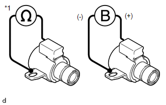
(b) Measure the resistance according to the value(s) in the table below.
Standard Resistance:
| Tester Connection | Condition | Specified Condition |
|---|---|---|
| Solenoid (SL) valve connector terminal - Solenoid (SL) valve body | 20°C (68°F) | 11 to 15 Ω |
(c) Connect a positive (+) lead from the battery to the terminal of the solenoid valve connector, and a negative (-) lead to the solenoid body. Check that the valve moves and makes an operating sound.
OK:
Valve moves and makes an operating sound.
| OK | | REPAIR OR REPLACE TRANSMISSION WIRE |
| NG | | REPLACE SOLENOID (SL) VALVE |
READ NEXT:
 Pressure Control Solenoid "A" Circuit Short to Battery (P074512)
DESCRIPTION Changing gears is performed by the ECM turning the solenoid (SL1, SL2, SL3, SL4, SL5 and SL6) valves on and off. If an open or short occurs in any of the solenoid valve circuits, the ECM c
Pressure Control Solenoid "A" Circuit Short to Ground or Open (P074514)
DESCRIPTION Refer to DTC P074512. Click here DTC No. Detection Item DTC Detection Condition Trouble Area MIL Memory Note P074514 Pressure Control Solenoid "A" Circuit Short to G
Pressure Control Solenoid "B" Circuit Short to Battery (P077512)
DESCRIPTION Changing gears is performed by the ECM turning the solenoid (SL1, SL2, SL3, SL4, SL5 and SL6) valves on and off. If an open or short occurs in any of the solenoid valve circuits, the ECM c
SEE MORE:
Check Bus 3 Line for Short to GND
DESCRIPTION There may be a short circuit between one of the CAN bus lines and GND when there is no resistance between terminal 6 (CA3H) of the central gateway ECU (network gateway ECU) and terminal 4 (CG) of the DLC3, or terminal 21 (CA3L) of the central gateway ECU (network gateway ECU) and termina
Lost Communication With ECM/PCM "A" (U0100,...,U1117)
DESCRIPTION These DTCs are stored if a CAN communication malfunction occurs between the main body ECU (multiplex network body ECU) and other ECUs. DTC No. Detection Item DTC Detection Condition Trouble Area DTC Output from U0100 Lost Communication With ECM/PCM "A" The main body EC
