Lexus ES: Terminals Of Ecu
TERMINALS OF ECU
CHECK AIR CONDITIONING AMPLIFIER ASSEMBLY
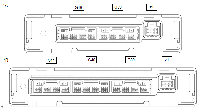
| *A | w/o Seat Heater | *B | w/ Seat Heater |
(a) Disconnect the G39 air conditioning amplifier assembly connector.
(b) Measure the voltage and resistance according to the value(s) in the table below.
HINT:
Measure the values on the wire harness side with the connector disconnected.
| Terminal No. (Symbol) | Wiring Color | Terminal Description | Condition | Specified Condition |
|---|---|---|---|---|
| G39-2 (IG+) - G39-4 (GND) | R - W-B | Power source (IG) | Engine switch on (IG) | 11 to 14 V |
| G39-2 (IG+) - G39-4 (GND) | R - W-B | Power source (IG) | Engine switch off | Below 1 V |
| G39-1 (B) - G39-4 (GND) | B - W-B | Battery power supply | Always | 11 to 14 V |
| G39-4 (GND) - Body ground | W-B - Body ground | Ground | Always | Below 1 Ω |
(c) Reconnect the G39 air conditioning amplifier assembly connector.
(d) Measure the voltage according to the value(s) in the table below.
| Terminal No. (Symbol) | Wiring Color | Terminal Description | Condition | Specified Condition |
|---|---|---|---|---|
| G39-17 (FDEF) - G39-4 (GND) | GR - W-B | Wiper Deicer signal | Engine switch on (IG), Front wiper deicer switch off | 11 to 14 V |
| G39-17 (FDEF) - G39-4 (GND) | GR - W-B | Wiper Deicer signal | Engine switch on (IG), Front wiper deicer switch on | Below 2.2 V |
READ NEXT:
 Diagnosis System
DIAGNOSIS SYSTEM CHECK DLC3 (a) Check the DLC3. Click here INSPECT BATTERY VOLTAGE (a) Measure the battery voltage. Standard Voltage: 11 to 14 V If the voltage is below 11 V, recharge or replace th
Data List / Active Test
DATA LIST / ACTIVE TEST ACTIVE TEST HINT: Using the Techstream to perform Active Tests allows relays, VSVs, actuators and other items to be operated without removing any parts. This non-intrusive func
Windshield Deicer does not Operate
DESCRIPTION When the front wiper deicer switch is operated, the operation signal is transmitted to the air conditioning amplifier assembly directly. When the air conditioning amplifier assembly receiv
SEE MORE:
Components
COMPONENTS ILLUSTRATION *1 DRIVE MODE SELECT SWITCH (COMBINATION SWITCH ASSEMBLY) *2 INSTRUMENT CLUSTER FINISH PANEL ASSEMBLY
Vehicle Approaching Sound ECU Communication Stop Mode
DESCRIPTION Detection Item Symptom Trouble Area Vehicle Approaching Sound ECU Communication Stop Mode Any of the following conditions are met:
Communication stop for "Vehicle Proximity Notification System" is indicated on the "Communication Bus Check" screen of the Techstream.
Click
