Lexus ES: Terminals Of Ecu
TERMINALS OF ECU
CHECK AIR CONDITIONING AMPLIFIER ASSEMBLY
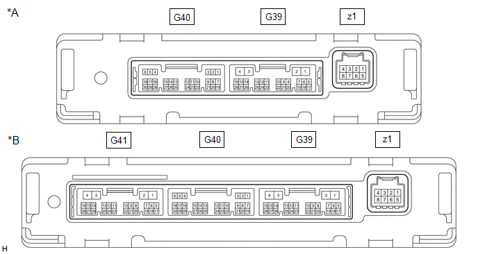
| *A | w/o Seat Heater | *B | w/ Seat Heater |
(a) Disconnect the G39 air conditioning amplifier assembly connector.
(b) Measure the voltage and resistance according to the value(s) in the table below.
HINT:
Measure the values on the wire harness side with the connector disconnected.
| Terminal No. (Symbol) | Wiring Color | Terminal Description | Condition | Specified Condition |
|---|---|---|---|---|
| G39-2 (IG+) - G39-4 (GND) | R - W-B | Power source (IG) | Engine switch on (IG) | 11 to 14 V |
| G39-2 (IG+) - G39-4 (GND) | R - W-B | Power source (IG) | Engine switch off | Below 1 V |
| G39-1 (B) - G39-4 (GND) | B - W-B | Battery power supply | Always | 11 to 14 V |
| G39-4 (GND) - Body ground | W-B - Body ground | Ground | Always | Below 1 Ω |
(c) Reconnect the G39 air conditioning amplifier assembly connector.
(d) Measure the voltage according to the value(s) in the table below.
| Terminal No. (Symbol) | Wiring Color | Terminal Description | Condition | Specified Condition |
|---|---|---|---|---|
| G39-17 (FDEF) - G39-4 (GND) | GR - W-B | Wiper Deicer signal | Engine switch on (IG), Front wiper deicer switch off | 11 to 14 V |
| G39-17 (FDEF) - G39-4 (GND) | GR - W-B | Wiper Deicer signal | Engine switch on (IG), Front wiper deicer switch on | Below 2.2 V |
READ NEXT:
 Diagnosis System
DIAGNOSIS SYSTEM CHECK DLC3 (a) Check the DLC3. Click here INSPECT BATTERY VOLTAGE (a) Measure the battery voltage. Standard Voltage: 11 to 14 V If the voltage is below 11 V, recharge or replace th
Data List / Active Test
DATA LIST / ACTIVE TEST ACTIVE TEST HINT: Using the Techstream to perform Active Tests allows relays, VSVs, actuators and other items to be operated without removing any parts. This non-intrusive func
Windshield Deicer does not Operate
DESCRIPTION When the front wiper deicer switch is operated, the operation signal is transmitted to the air conditioning amplifier assembly directly. When the air conditioning amplifier assembly receiv
SEE MORE:
Steering Sensor Signal Malfunction (C1784)
DESCRIPTION Steering sensor signals are sent to the absorber control ECU via CAN communication. If a communication error is detected, DTC C1784 is stored. DTC No. Detection Item DTC Detection Condition Trouble Area Warning Indicate Memory C1784 Steering Sensor Signal Malfunction
Mechanical System Tests
MECHANICAL SYSTEM TESTS STALL SPEED TEST CAUTION:
Do not perform a stall test if there are any people or objects near the vehicle.
The vehicle could begin moving suddenly, resulting in a serious accident.
Do not perform a stall test if any wheel chocks are out of position.
The vehicle
