Lexus ES: Terminals Of Ecu
TERMINALS OF ECU
NOTICE:
- DTCs may be output when connectors are disconnected during inspection. Therefore, be sure to clear the DTCs using the Techstream once the inspection has been completed.
- Do not apply excessive force to the forward recognition camera connector.

CHECK FORWARD RECOGNITION CAMERA
(a) Measure the voltage and resistance according to the value(s) in the table below.
| Terminal No. (Symbol) | Wiring Color | Terminal Description | Condition | Specified Condition |
|---|---|---|---|---|
| P5-7 (IGB) - P5-10 (GND) | LA-P - LA | Power source | Engine switch on (IG) | 11 to 14 V |
| Engine switch off | Below 1 V | |||
| P5-1 (HTR) - P5-10 (GND) | B - LA | Forward recognition with heater hood sub-assembly operation signal | Engine switch on (IG) Forward recognition with heater hood sub-assembly not operating | 11 to 14 V |
| Engine switch on (IG) Forward recognition with heater hood sub-assembly operating | Below 1 V | |||
| P5-10 (GND) - Body ground | LA - Body ground | Ground | Always | Below 1 Ω |
(b) Measure the waveform according to the value(s) in the table below.
| Terminal No. (Symbol) | Wiring Color | Terminal Description | Condition | Specified Condition |
|---|---|---|---|---|
| P5-2 (STRV) - P5-10 (GND) | P - LA | LIN communication signal | Engine switch on (IG) | Pulse generation |
(c) Check for pulses according to the value(s) in the table below.
HINT:
If the waveform is not similar to that shown in the illustration, a malfunction of a CAN bus line, terminating resistor, or the forward recognition camera is suspected.
| Terminal No. (Symbol) | Wiring Color | Terminal Description | Condition | Specified Condition |
|---|---|---|---|---|
| P5-5 (CA1P) - P5-10 (GND) | L - LA | CAN communication signal | Engine switch on (IG) | Pulse generation (See waveform 1) |
| P5-11 (CA1N) - P5-10 (GND) | W - LA | CAN communication signal | Engine switch on (IG) | Pulse generation (See waveform 2) |
| P5-6 (CANH) - P5-10 (GND) | B - LA | CAN communication signal | Engine switch on (IG) | Pulse generation (See waveform 1) |
| P5-12 (CANL) - P5-10 (GND) | W - LA | CAN communication signal | Engine switch on (IG) | Pulse generation (See waveform 2) |
(1) WAVEFORM 1
| Item | Content |
|---|---|
| Terminal Name | Between P5-5 (CA1P) and P5-10 (GND) Between P5-6 (CANH) and P5-10 (GND) |
| Tester Range | 1 V/DIV., 10 μs/DIV. |
| Condition | Engine switch on (IG) |
HINT:
The waveform varies depending on the CAN communication signal.
.png)
(2) WAVEFORM 2
| Item | Content |
|---|---|
| Terminal Name | Between P5-11 (CA1N) and P5-10 (GND) Between P5-12 (CANL) and P5-10 (GND) |
| Tester Range | 1 V/DIV., 10 μs/DIV. |
| Condition | Engine switch on (IG) |
HINT:
The waveform varies depending on the CAN communication signal.
.png)
NOTICE:
DTCs may be output when connectors are disconnected during inspection. Therefore, be sure to clear the DTCs using the Techstream once the inspection has been completed.
CHECK STEERING VIBRATION ECU
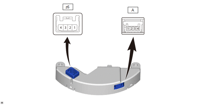
(a) Measure the voltage and resistance according to the value(s) in the table below.
| Terminal No. (Symbol) | Terminal Description | Condition | Specified Condition |
|---|---|---|---|
| z6-4 (IG) - z6-1 (GND) | Power source | Engine switch on (IG) | 11 to 14 V |
| Engine switch off | Below 1 V | ||
| z6-1 (GND) - Body ground | Ground | Always | Below 1 Ω |
| A-1 (M+) - z6-1 (GND) | Steering vibration operation signal | Engine switch on (IG) Steering vibration operating | Pulse generation |
| Engine switch on (IG) Steering vibration not operating | Below 1 V |
(b) Measure the waveform according to the value(s) in the table below.
| Terminal No. (Symbol) | Terminal Description | Condition | Specified Condition |
|---|---|---|---|
| z6-2(LIN1) - z6-1(GND) | LIN communication signal | Engine switch on (IG) | Pulse generation |
READ NEXT:
 Diagnosis System
DIAGNOSIS SYSTEM DIAGNOSIS FUNCTION (a) If a malfunction is detected in the forward recognition camera, the forward recognition camera stores a DTC without directly informing the driver via indicator
Dtc Check / Clear
DTC CHECK / CLEAR CHECK DTC (a) Connect the Techstream to the DLC3. (b) Turn the engine switch on (IG). (c) Turn the Techstream on. (d) Enter the following menus: Chassis > Front Recognition Camera
Freeze Frame Data
FREEZE FRAME DATA DESCRIPTION (a) Whenever a front camera system DTC is stored, the forward recognition camera stores the current vehicle state (ECU and sensor information) as Freeze Frame Data. CHECK
SEE MORE:
Coolant
ComponentsCOMPONENTS ILLUSTRATION *1 RADIATOR CAP SUB-ASSEMBLY *2 RADIATOR DRAIN COCK PLUG *3 NO. 1 ENGINE UNDER COVER - - ReplacementREPLACEMENT CAUTION / NOTICE / HINT CAUTION: Do not remove the radiator cap sub-assembly or radiator drain cock plug while the engine and rad
On-vehicle Inspection
ON-VEHICLE INSPECTION PROCEDURE 1. INSPECT WASHER NOZZLE SUB-ASSEMBLY (a) Operate the washer nozzle sub-assemblies and check the position that the washer fluid contacts the windshield. Standard: Center of washer fluid contacts the windshield in the areas shown in the illustration. *a Upper Li
