Lexus ES: Removal
REMOVAL
CAUTION / NOTICE / HINT
The necessary procedures (adjustment, calibration, initialization, or registration) that must be performed after parts are removed and installed, or replaced during cylinder head gasket removal/installation are shown below.
Necessary Procedure After Parts Removed/Installed/Replaced| Replaced Part or Performed Procedure | Necessary Procedure | Effect/Inoperative Function when Necessary Procedure not Performed | Link |
|---|---|---|---|
| Auxiliary battery terminal is disconnected/reconnected | Perform steering sensor zero point calibration | Lane control system (for HV Model) | |
| Pre-collision system (for HV Model) | |||
| Parking support brake system (for HV Model)* | |||
| Lighting system (for HV Model) | |||
| Memorize steering angle neutral point | Parking assist monitor system (for HV Model) | | |
| Panoramic view monitor system (for HV Model) | | ||
| Initialize power trunk lid system | Power trunk lid system (for HV Model) | | |
| Replacement of ECM | Perform Vehicle Identification Number (VIN) registration | MIL illuminates | |
| Inspection After Repair |
| |
| Replacement of inverter with converter assembly | Resolver learning |
| |
| Replacement of hybrid vehicle transaxle assembly |
| ||
| Front wheel alignment adjustment |
|
| |
|
|
| |
| Suspension, tires, etc.*1 | Rear television camera assembly optical axis (Back camera position setting) | Parking assist monitor system (for HV Model) | |
| Replacement of front bumper assembly | Front television camera view adjustment | Panoramic view monitor system (for HV Model) | |
| Suspension, tires, etc.*1 |
| ||
| Replacement of headlight ECU sub-assembly LH |
| Lighting system (for HV Model) | |
| Suspension, tires, etc.*1 | Perform headlight ECU sub-assembly LH initialization*2 |
-
*: When performing learning using the Techstream.
Click here
.gif)
- *1: If the vehicle height has changed due to suspension or tire replacement.
- *2: for LED type turn signal light
NOTICE:
- After the power switch is turned off, the radio receiver assembly records various types of memory and settings. As a result, after turning the power switch off, make sure to wait at least 85 seconds before disconnecting the cable from the negative (-) auxiliary battery terminal. (for Audio and Visual System)
- After the power switch is turned off, the radio receiver assembly records various types of memory and settings. As a result, after turning the power switch off, make sure to wait at least 85 seconds before disconnecting the cable from the negative (-) auxiliary battery terminal. (for Navigation System)
-
This procedure includes the removal of small-head bolts. Refer to Small-Head Bolts of Basic Repair Hint to identify the small-head bolts.
Click here
PROCEDURE
1. INSTALL ENGINE ASSEMBLY TO ENGINE STAND
Click here
2. REMOVE ENGINE HANGERS
Click here
3. REMOVE COMPRESSOR WITH MOTOR ASSEMBLY
Click here
4. REMOVE NO. 2 WATER BY-PASS PIPE SUB-ASSEMBLY
Click here
5. REMOVE FLOW SHUTTING VALVE (WATER BY-PASS HOSE ASSEMBLY)
Click here
6. REMOVE NO. 1 EXHAUST MANIFOLD HEAT INSULATOR
Click here
7. REMOVE MANIFOLD STAY
Click here
8. REMOVE EXHAUST MANIFOLD (TWC: Front Catalyst)
Click here
9. REMOVE THROTTLE BODY WITH MOTOR ASSEMBLY
Click here
10. REMOVE THROTTLE BODY GASKET
Click here
11. REMOVE EGR COOLER ASSEMBLY
Click here
12. REMOVE NO. 1 EGR PIPE SUB-ASSEMBLY
Click here
13. REMOVE NO. 4 WATER BY-PASS HOSE
Click here
14. REMOVE EGR VALVE ASSEMBLY
Click here
15. REMOVE NO. 3 WATER BY-PASS PIPE
Click here
16. REMOVE NO. 2 WATER BY-PASS PIPE
Click here
17. REMOVE INTAKE MANIFOLD
Click here
18. REMOVE NO. 1 INTAKE MANIFOLD TO HEAD GASKET
Click here
19. DISCONNECT FUEL TUBE SUB-ASSEMBLY
Click here
20. REMOVE NO. 1 FUEL PIPE SUB-ASSEMBLY
Click here
21. REMOVE FUEL PUMP ASSEMBLY (for High Pressure)
Click here
22. REMOVE NO. 7 WATER BY-PASS HOSE
Click here
23. REMOVE FUEL DELIVERY PIPE SUB-ASSEMBLY
Click here
24. REMOVE NO. 1 DELIVERY PIPE SPACER
Click here
25. REMOVE INJECTOR VIBRATION INSULATOR
Click here
26. REMOVE NO. 5 ENGINE WIRE
Click here
27. REMOVE PORT FUEL INJECTOR ASSEMBLY
Click here
28. REMOVE FUEL DELIVERY PIPE
Click here
29. REMOVE DIRECT FUEL INJECTOR ASSEMBLY
Click here
30. REMOVE IGNITION COIL ASSEMBLY
Click here
31. REMOVE ENGINE OIL LEVEL DIPSTICK GUIDE
Click here
32. REMOVE OIL PRESSURE CONTROL VALVE ASSEMBLY
Click here
33. REMOVE CAMSHAFT POSITION SENSOR (for Intake Side)
Click here
34. REMOVE CAMSHAFT POSITION SENSOR (for Exhaust Side)
Click here
35. REMOVE CAM TIMING OIL CONTROL SOLENOID ASSEMBLY
Click here
36. REMOVE O-RING
Click here
37. REMOVE CAM TIMING CONTROL MOTOR WITH EDU ASSEMBLY
Click here
38. REMOVE CAM TIMING CONTROL MOTOR O-RING
Click here
39. REMOVE CRANKSHAFT PULLEY ASSEMBLY
Click here
40. REMOVE WATER OUTLET
Click here
41. REMOVE WATER BY-PASS OUTLET SUB-ASSEMBLY
Click here
42. REMOVE CYLINDER HEAD COVER SUB-ASSEMBLY
Click here
43. REMOVE SPARK PLUG TUBE GASKET
Click here
44. REMOVE ENGINE MOUNTING BRACKET RH
Click here
45. REMOVE NO. 2 TIMING CHAIN COVER ASSEMBLY
Click here
46. REMOVE TIMING CHAIN COVER OIL SEAL
Click here
47. SET NO. 1 CYLINDER TO TDC (COMPRESSION)
Click here
48. REMOVE OIL PUMP DRIVE CHAIN SUB-ASSEMBLY
Click here
49. REMOVE CAMSHAFT TIMING GEAR ASSEMBLY
Click here
50. REMOVE CHAIN SUB-ASSEMBLY
Click here
51. REMOVE NO. 1 CHAIN TENSIONER ASSEMBLY
Click here
52. REMOVE CHAIN TENSIONER SLIPPER
Click here
53. REMOVE NO. 1 CHAIN VIBRATION DAMPER
Click here
54. REMOVE CAMSHAFT TIMING EXHAUST GEAR ASSEMBLY
Click here
55. REMOVE TIMING CHAIN COVER ASSEMBLY
Click here
56. REMOVE FUEL PUMP LIFTER GUIDE
Click here
57. REMOVE CAMSHAFT HOUSING SUB-ASSEMBLY
Click here
58. REMOVE CAMSHAFT BEARING CAP
Click here
59. REMOVE CAMSHAFT
Click here
60. REMOVE NO. 2 CAMSHAFT
Click here
61. REMOVE NO. 1 VALVE ROCKER ARM SUB-ASSEMBLY
Click here
62. REMOVE VALVE LASH ADJUSTER ASSEMBLY
Click here
63. REMOVE VALVE STEM CAP
Click here
64. REMOVE CYLINDER HEAD SUB-ASSEMBLY
Click here
65. REMOVE CYLINDER HEAD GASKET
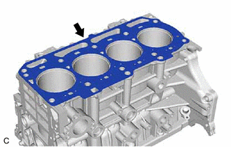
(a) Remove the cylinder head gasket from the cylinder block sub-assembly.
66. INSPECT CYLINDER HEAD SET BOLT
Click here
67. INSPECT CYLINDER HEAD SUB-ASSEMBLY
Click here
READ NEXT:
 Installation
INSTALLATION CAUTION / NOTICE / HINT NOTICE: This procedure includes the installation of small-head bolts. Refer to Small-Head Bolts of Basic Repair Hint to identify the small-head bolts. Click here
On-vehicle Inspection
ON-VEHICLE INSPECTION CAUTION / NOTICE / HINT CAUTION: To prevent injury due to contact with an operating cooling fan, keep your hands and clothing away from the cooling fans when working in the engin
SEE MORE:
Components
COMPONENTS ILLUSTRATION *1 FRONT FENDER APRON SEAL RH *2 V-BANK COVER SUB-ASSEMBLY N*m (kgf*cm, ft.*lbf): Specified torque - - ILLUSTRATION *1 CAMSHAFT TIMING GEAR BOLT *2 O-RING *3 CAMSHAFT TIMING OIL CONTROL SOLENOID ASSEMBLY (for Exhaust Side of Bank 2) -
Drive Start Control
DESCRIPTION The drive start control is controlled by the hybrid vehicle control ECU. If the hybrid vehicle control ECU determines that the shift lever and accelerator pedal are operated abnormally, hybrid system output is restricted and, when necessary, a warning is displayed on the combination mete
