Lexus ES: System Diagram
SYSTEM DIAGRAM
READ NEXT:
 Terminals Of Ecu
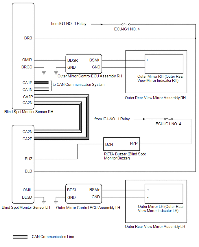
TERMINALS OF ECU BLIND SPOT MONITOR SENSOR RH Terminal No. (Symbol) Wiring Color Terminal Description Condition Specified Condition R4-4 (OMIR) - R4-10 (BRGD) SB - W-B Outer rear v
Lost Communication with ECM / PCM "A" (U0100,U0125,U0126,U0129,U0142,U0293)
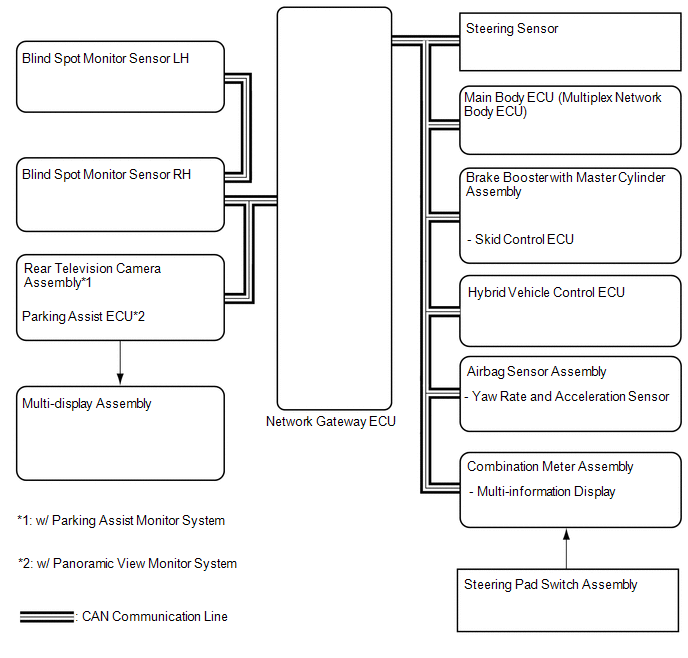
DESCRIPTION These DTCs are stored if there is a malfunction in the CAN communication system connected to the blind spot monitor sensor. HINT: If CAN communication system DTCs are stored, they may also
Lost Communication with Blind Spot Monitor Slave Module (U0232)
DESCRIPTION This DTC is stored when the blind spot monitor sensor RH judges that there is a communication problem with the blind spot monitor sensor LH. DTC No. Detection Item DTC Detection Con
SEE MORE:
Hybrid/EV Battery Stack 2 Cell Circuit Voltage Above Threshold (P1A6017,P31AA17)
DESCRIPTION The HV battery is composed of 70 cells (3.7 V each) in series. The battery ECU assembly monitors the voltage of each HV battery cell to detect malfunctions of the HV battery. DTC No. Detection Item DTC Detection Condition Trouble Area MIL Warning Indicate P1A6017 Hybri
Components
COMPONENTS
ILLUSTRATION
*1
RADIATOR CAP SUB-ASSEMBLY
*2
RADIATOR DRAIN COCK PLUG
*3
NO. 1 ENGINE UNDER COVER
-
-
© 2016-2026 Copyright www.lexguide.net
