Lexus ES: System Diagram
SYSTEM DIAGRAM
.png)
 w/ Parking Assist Monitor System
 .png) w/ Panoramic View Monitor System
w/ Panoramic View Monitor System .png) w/o Manual (SOS) Switch
w/o Manual (SOS) Switch 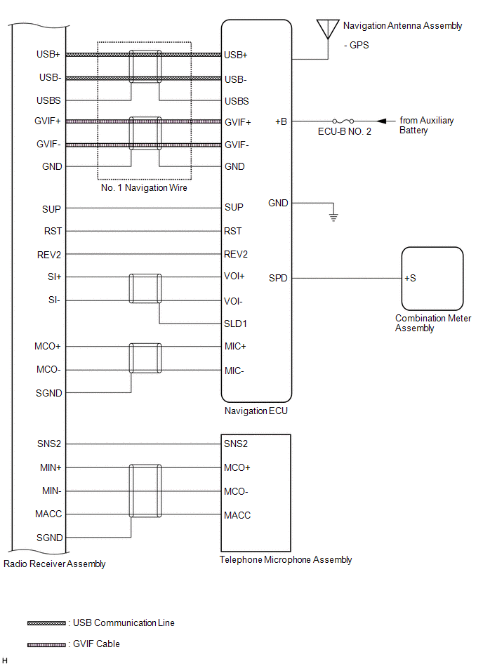 w/ Manual (SOS) Switch
 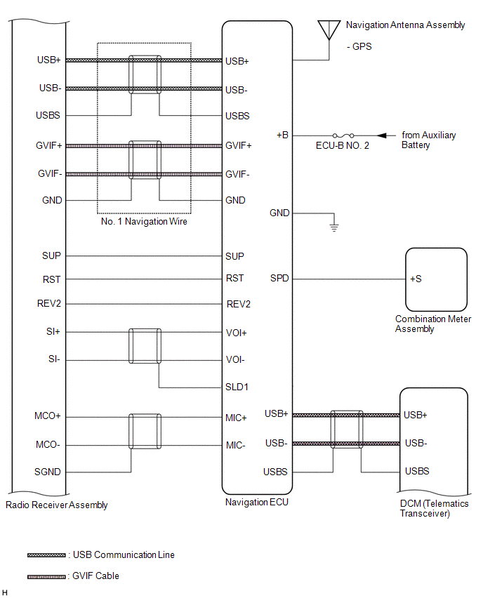 w/ Manual (SOS) Switch
 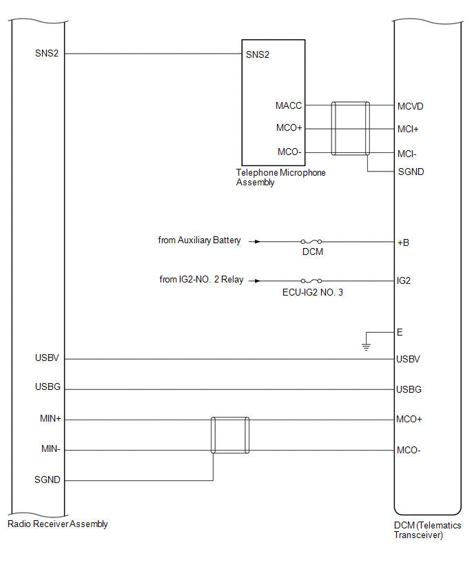 for 10 Speakers
 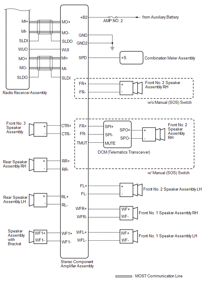 for 17 Speakers
 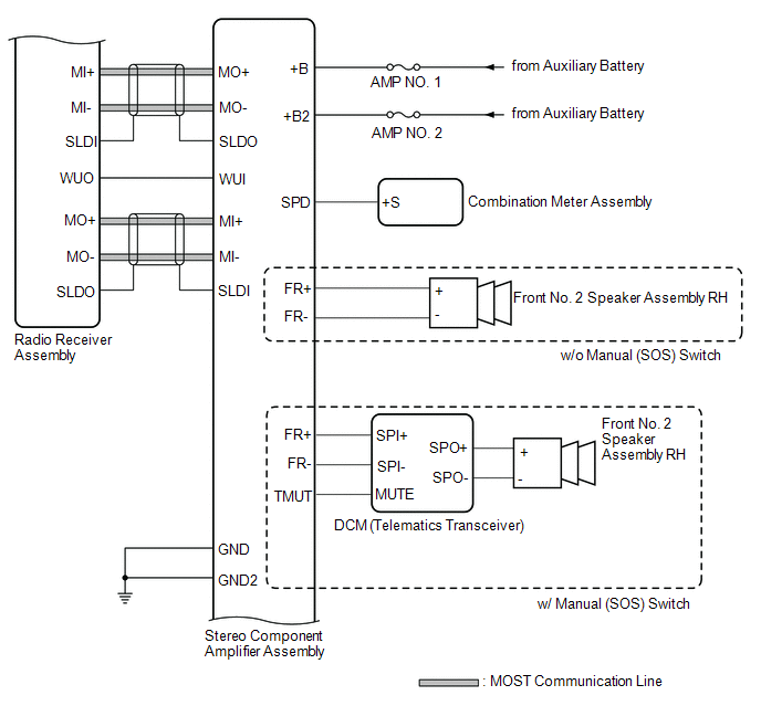 for 17 Speakers
 .png)
READ NEXT:
 Terminals Of Ecu
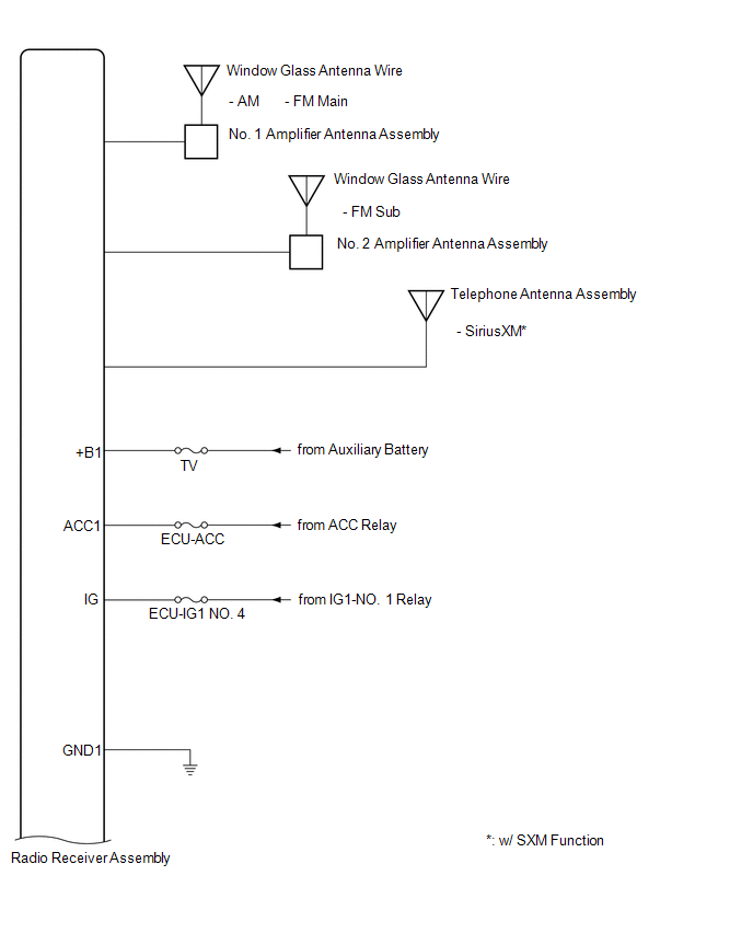
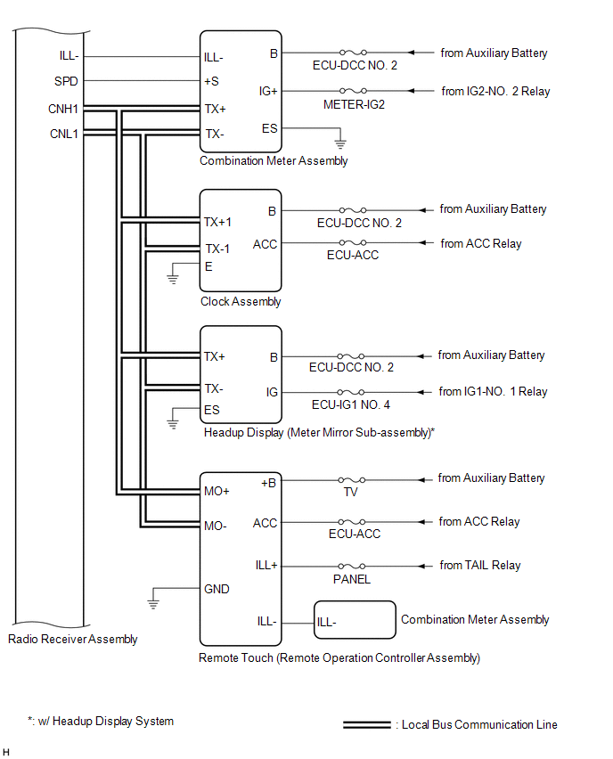
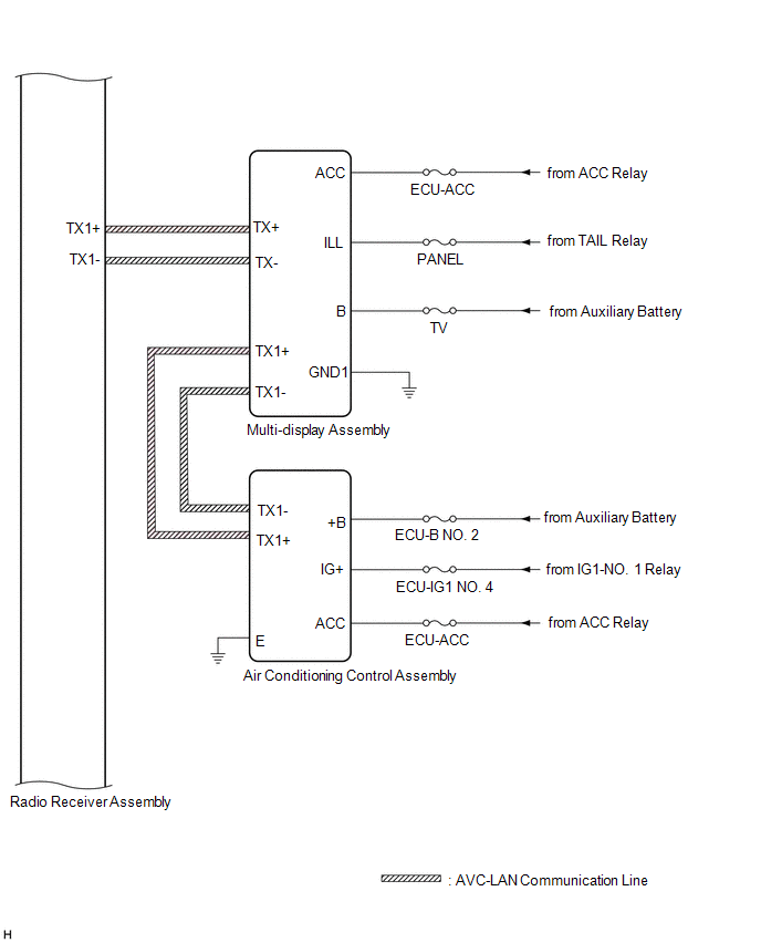
TERMINALS OF ECU HINT: Check from the rear of the connector while it is connected to the components. RADIO RECEIVER ASSEMBLY Terminal No. (Symbol) Wiring Color Terminal Description Condition
Sending Malfunction (Navigation to APGS) (U0073,U0100,U0129,U0140,U0155,U0164,U0198,U023B,U0265,U0293,U1110)
DESCRIPTION These DTCs are stored when a malfunction occurs in the CAN communication circuit. DTC No. Detection Item DTC Detection Condition Trouble Area U0073 Sending Malfunction (Navi
USB Audio System Recognition/Play Error
DESCRIPTION When a USB device or "iPod" is connected to the USB jack of the No. 1 stereo jack adapter assembly, it must have playable files. The device must also communicate with and be recognized by
SEE MORE:
Motor/Generator Shutdown Signal (Hybrid/EV Side) Stuck Off (P33B99F)
DTC SUMMARY MALFUNCTION DESCRIPTION The hybrid vehicle control ECU detects malfunctions which prevent the inverter with converter assembly emergency shutdown circuit (HSDN) from shutting down the hybrid control system. Detection is performed when the power switch is turned on (IG) and during the shu
Lost Communication with Cruise Control Front Distance Range Sensor Single Sensor or Center Missing Message (U023587)
DESCRIPTION The forward recognition camera communicates with the millimeter wave radar sensor assembly via CAN communication. If a communication malfunction between the forward recognition camera and millimeter wave radar sensor assembly is detected, DTC U023587 is stored. DTC No. Detection Ite
© 2016-2026 Copyright www.lexguide.net
