Lexus ES: No Response from Steering Lock ECU (B2786)
DESCRIPTION
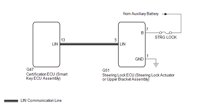
This DTC is stored when LIN communication between the certification ECU (smart key ECU assembly) and steering lock ECU (steering lock actuator or upper bracket assembly) stops for 10 seconds or more.
| DTC No. | Detection Item | DTC Detection Condition | Trouble Area |
|---|---|---|---|
| B2786 | No Response from Steering Lock ECU | No communication between steering lock ECU (steering lock actuator or upper bracket assembly) and certification ECU (smart key ECU assembly) for 10 seconds or more. |
|
WIRING DIAGRAM
CAUTION / NOTICE / HINT
NOTICE:
- Inspect the fuses for circuits related to this system before performing the following procedure.
- When using the Techstream with the power switch off, connect the Techstream to the DLC3 and turn a courtesy light switch on and off at intervals of 1.5 seconds or less until communication between the Techstream and the vehicle begins. Then select the vehicle type under manual mode and enter the following menus Body Electrical Smart Access. While using the Techstream, periodically turn a courtesy light switch on and off at intervals of 1.5 seconds or less to maintain communication between the Techstream and the vehicle.
-
Before replacing the certification ECU (smart key ECU assembly) or steering lock ECU (steering lock actuator or upper bracket assembly), refer to Registration.
Click here
.gif)
PROCEDURE
| 1. | CHECK HARNESS AND CONNECTOR (CERTIFICATION ECU (SMART KEY ECU ASSEMBLY) - STEERING LOCK ECU (STEERING LOCK ACTUATOR OR UPPER BRACKET ASSEMBLY)) |
(a) Disconnect the G47 certification ECU (smart key ECU assembly) connector.
(b) Disconnect the G51 steering lock ECU (steering lock actuator or upper bracket assembly) connector.
(c) Measure the resistance according to the value(s) in the table below.
NOTICE:
Make sure that each ECU is in sleep mode before performing the inspection. To enter sleep mode, turn the power switch from on (IG) to off and wait for 180 seconds or more without operating any switches.
Standard Resistance:
| Tester Connection | Condition | Specified Condition |
|---|---|---|
| G47-13 (LIN) - G51-5 (LIN) | Power switch off | Below 1 Ω |
| G47-13 (LIN) or G51-5 (LIN) - Body ground | Power switch off | 10 kΩ or higher |
| NG | .gif) | REPAIR OR REPLACE HARNESS OR CONNECTOR |
|
.gif)
| 2. | CHECK HARNESS AND CONNECTOR (STEERING LOCK ECU (STEERING LOCK ACTUATOR OR UPPER BRACKET ASSEMBLY) - AUXILIARY BATTERY, BODY GROUND) |
(a) Measure the voltage according to the value(s) in the table below.
Standard Voltage:
| Tester Connection | Condition | Specified Condition |
|---|---|---|
| G51-7 (B) - G51-1 (GND) | Power switch off | 11 to 14 V |
(b) Measure the resistance according to the value(s) in the table below.
Standard Resistance:
| Tester Connection | Condition | Specified Condition |
|---|---|---|
| G51-1 (GND) - Body ground | Always | Below 1 Ω |
| NG | | REPAIR OR REPLACE HARNESS OR CONNECTOR |
|
| 3. | REPLACE STEERING LOCK ECU (STEERING LOCK ACTUATOR OR UPPER BRACKET ASSEMBLY) |
(a) Replace the steering lock ECU (steering lock actuator or upper bracket assembly).
Click here
|
| 4. | REGISTER ECU CODE REGISTRATION |
(a) Register the recognition codes in the ECUs.
Click here
|
| 5. | CHECK FOR DTC |
(a) Clear the DTCs.
Body Electrical > Smart Access > Clear DTCs(b) Recheck for DTCs.
Body Electrical > Smart Access > Trouble CodesOK:
DTC B2786 is not output.
| OK | | END (STEERING LOCK ECU (STEERING LOCK ACTUATOR OR UPPER BRACKET ASSEMBLY) WAS DEFECTIVE) |
| NG | | REPLACE CERTIFICATION ECU (SMART KEY ECU ASSEMBLY) |
READ NEXT:
 Communication Malfunction between ECUs Connected by LIN (B2785)
DESCRIPTION If the certification ECU (smart key ECU assembly) detects a communication error with an ECU connected to the certification bus lines for 7 seconds or more, DTC B2785 will be stored. DTC
LIN Communication Bus Malfunction (B2325)
DESCRIPTION If the main body ECU (multiplex network body ECU) detects a communication error with an ECU connected to the door bus lines for 8 seconds or more, DTC B2325 will be stored. DTC No. De
P/W Master Switch Communication Stop (B1206,B1273,B2321-B2324)
DESCRIPTION This DTC is stored when LIN communication between the main body ECU (multiplex network body ECU) and multiplex network master switch assembly, sliding roof ECU (sliding roof drive gear sub
SEE MORE:
Repair
REPAIR CAUTION / NOTICE / HINT HINT:
Use the same procedure for the RH side and LH side.
The following procedure is for the LH side.
If the installation area of the headlight assembly is damaged, use a supply retainer for a low-cost repair.
Ensure that the headlight assembly is not damaged.
Diagnostic Trouble Code Chart
DIAGNOSTIC TROUBLE CODE CHART Dynamic Radar Cruise Control System DTC No. Detection Item MIL DTC Output from Link P057113 Brake Switch "A" Circuit Open Does not come on ECM P057162 Brake Switch "A" Signal Compare Failure Does not come on Engine P057504
