Lexus ES: System Diagram
Lexus ES (XZ10) Service Manual / Vehicle Interior / Window / Glass / Window Defogger System (for Hv Model) / System Diagram
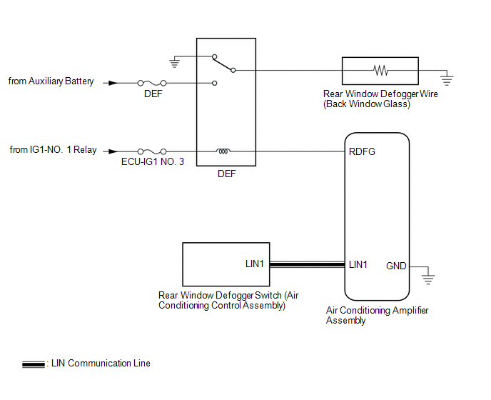
SYSTEM DIAGRAM
 Communication Table
 | Transmitter | Receiver | Signal | Communication Method |
|---|---|---|---|
| Rear Window Defogger Switch (Air Conditioning Control Assembly) | Air Conditioning Amplifier Assembly | Rear Window Defogger Switch Signal | LIN |
READ NEXT:
 System Description
SYSTEM DESCRIPTION GENERAL (a) The rear window defogger wire (back window glass) is attached to the inside of the rear window and defogs the window surface quickly when the rear window defogger switch
How To Proceed With Troubleshooting
CAUTION / NOTICE / HINT HINT:
Use the following procedure to troubleshoot the window defogger system.
*: Use the Techstream.
PROCEDURE 1. VEHICLE BROUGHT TO WORKSHOP
NEXT
Operation Check
OPERATION CHECK CHECK WINDOW DEFOGGER SYSTEM (a) Turn the power switch on (IG). (b) Check that the rear window defogger wire becomes warm by operating the rear window defogger switch of the air condit
SEE MORE:
Installation
INSTALLATION PROCEDURE 1. INSTALL FLOW SHUTTING VALVE (WATER BY-PASS HOSE ASSEMBLY) (a) Connect the flow shutting valve (water by-pass hose assembly) to the transmission oil cooler and slide the clip to secure it. *a 2 to 7 mm (0.0787 to 0.276 in.) *b Paint Mark *c 45° (Tabs of Clip
Components
COMPONENTS ILLUSTRATION *1 REAR DRIVE SHAFT ASSEMBLY LH *2 REAR DRIVE SHAFT INBOARD JOINT SHAFT SNAP RING LH *3 REAR DIFFERENTIAL CARRIER ASSEMBLY - - Toyota Genuine Differential Gear Oil LT 75W-85 API GL-5 MP grease Do not apply lubricants to the threaded part
© 2016-2026 Copyright www.lexguide.net
