Lexus ES: System Diagram
SYSTEM DIAGRAM
 Communication Table
 | Transmitting ECU | Receiving ECU | Signal | Communication Method |
|---|---|---|---|
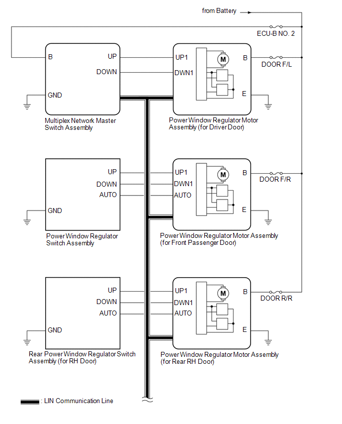
| Multiplex Network Master Switch Assembly | Power Window Regulator Motor Assembly (for Driver Door) | Power window auto up and down signal | LIN |
| Power window remote up and down signal | LIN | |
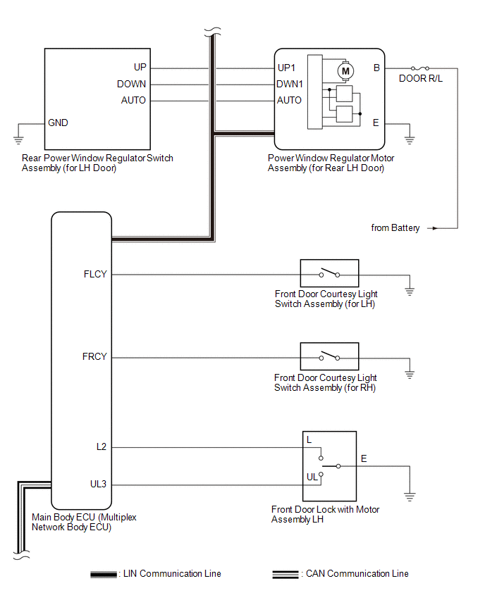
| Main Body ECU (Multiplex Network Body ECU) |
| Power window operation permission signal | LIN |
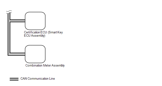
| Certification ECU (Smart Key ECU Assembly) | Main Body ECU (Multiplex Network Body ECU) | Wireless power window operation signal | CAN |
| Main Body ECU (Multiplex Network Body ECU) | Combination Meter Assembly | Window open warning request signal | CAN |
READ NEXT:
 System Description
SYSTEM DESCRIPTION POWER WINDOW CONTROL SYSTEM DESCRIPTION (a) The power window control system controls the power window operation using the power window regulator motor assemblies. The main controls
How To Proceed With Troubleshooting
CAUTION / NOTICE / HINT HINT:
Use the following procedure to troubleshoot the power window control system.
*: Use the Techstream.
PROCEDURE 1. VEHICLE BROUGHT TO WORKSHOP
NEXT
Operation Check
OPERATION CHECK CHECK WINDOW LOCK FUNCTION HINT: Before performing the window lock switch operation check, make sure that the window lock switch is off (the switch is not pushed in). (a) Turn the win
SEE MORE:
Knock Sensor 1 Bank 1 or Single Sensor Circuit Short to Ground (P032511)
DESCRIPTION A flat-type knock control sensor (non-resonant type) has a structure that can detect vibrations between approximately 5 and 23 kHz. The knock control sensor is fitted onto the engine block to detect engine knocking. The knock control sensor contains a piezoelectric element which generate
12-volt battery
Location
The 12-volt battery is located on the
right-hand side of the trunk.
■Before recharging
When recharging, the 12-volt battery produces
hydrogen gas which is flammable
and explosive. Therefore, observe the following
precautions before recharging:
If recharging with the 12-volt b
© 2016-2026 Copyright www.lexguide.net
