Lexus ES: System Diagram
SYSTEM DIAGRAM
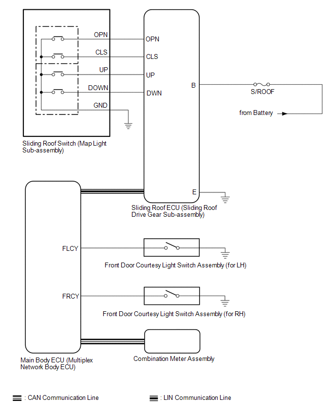 Communication Table
 | Sender | Receiver | Signal | Line |
|---|---|---|---|
| Main Body ECU (Multiplex Network Body ECU) | Sliding Roof ECU (Sliding Roof Drive Gear Sub-assembly) |
| LIN |
| Sliding Roof ECU (Sliding Roof Drive Gear Sub-assembly) | Main Body ECU (Multiplex Network Body ECU) | Sliding roof position signal | LIN |
| Combination Meter Assembly | Main Body ECU (Multiplex Network Body ECU) | Vehicle speed signal | CAN |
| Main Body ECU (Multiplex Network Body ECU) | Combination Meter Assembly | Sliding roof open warning request signal | CAN |
READ NEXT:
 System Description
SYSTEM DESCRIPTION SLIDING ROOF SYSTEM DESCRIPTION (a) The sliding roof system controls the sliding roof operation using the sliding roof ECU (sliding roof drive gear sub-assembly). Operating the slid
How To Proceed With Troubleshooting
CAUTION / NOTICE / HINT HINT:
Use the following procedure to troubleshoot the sliding roof system.
*: Use the Techstream.
PROCEDURE 1. VEHICLE BROUGHT TO WORKSHOP
NEXT
Operation Check
OPERATION CHECK CHECK AUTO OPERATION FUNCTION NOTICE:
Make sure that initialization has been completed before performing this inspection.
Click here
The sliding roof auto operation can be custo
SEE MORE:
Diagnostic Trouble Code Chart
DIAGNOSTIC TROUBLE CODE CHART Audio and Visual System DTC No. Detection Item Link B1323 Lost Communication with Haptic Device B1324 Lost Communication with Meter B1326 Lost Communication with Clock Device (Local-CAN) B1551 HD Radio Tuner Malfunction
Pressure Control Solenoid "L" Circuit Short to Ground or Open (P08BA14)
DESCRIPTION Refer to DTC P08BA12. Click here DTC No. Detection Item DTC Detection Condition Trouble Area MIL Memory Note P08BA14 Pressure Control Solenoid "L" Circuit Short to Ground or Open While the vehicle is being driven so that gear changes occur, a short to ground or o
© 2016-2026 Copyright www.lexguide.net
