Lexus ES: System Diagram
SYSTEM DIAGRAM
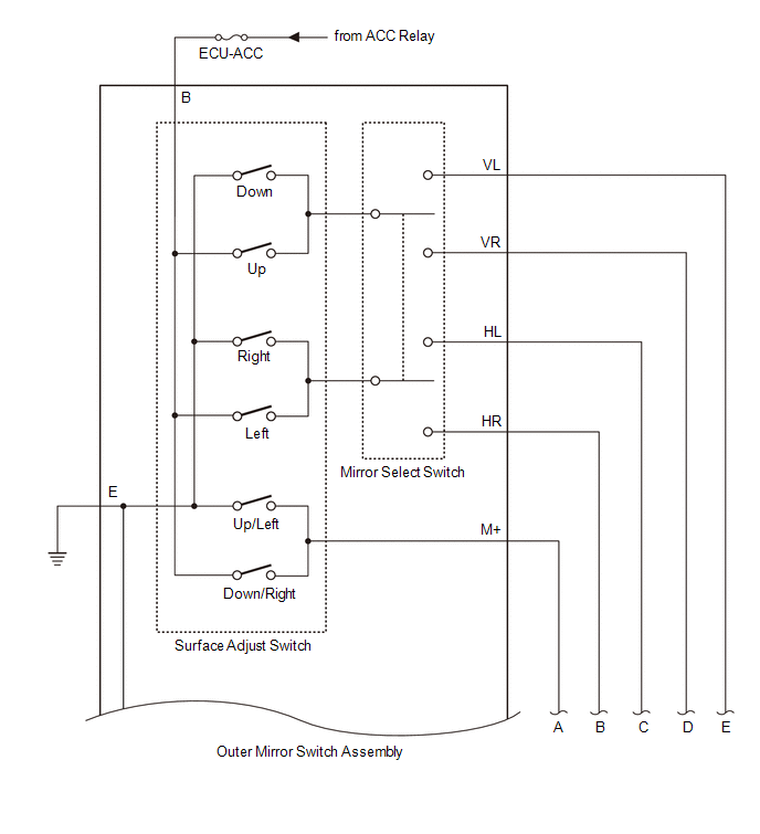
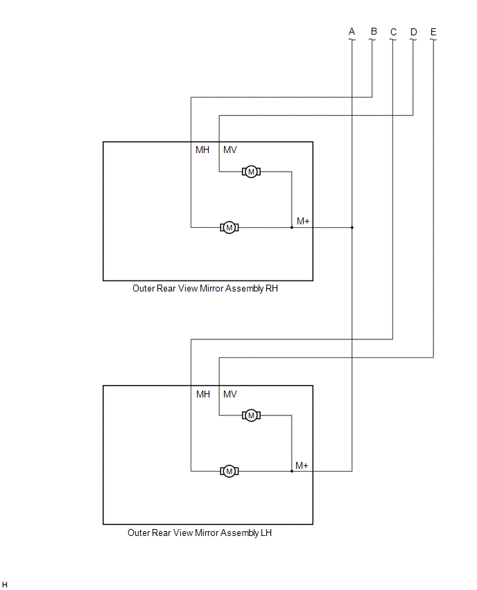
ELECTRICAL REMOTE CONTROL MIRROR FUNCTION
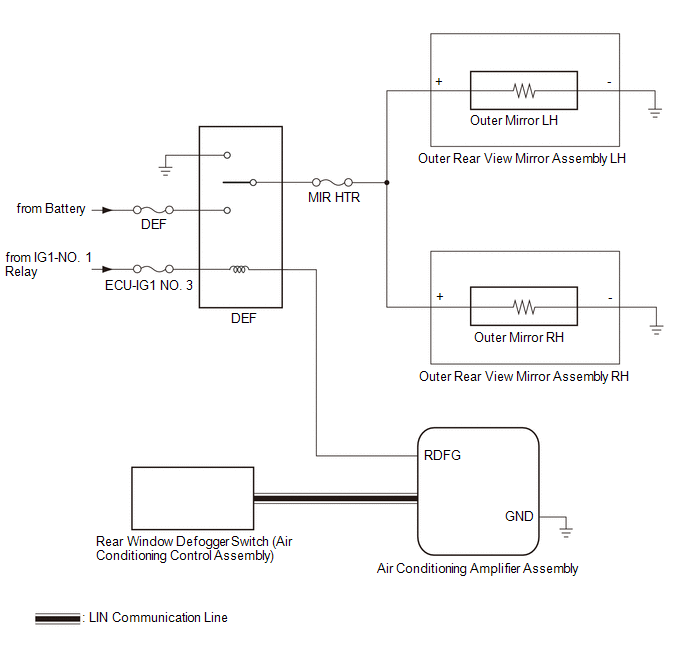
MIRROR HEATER FUNCTION
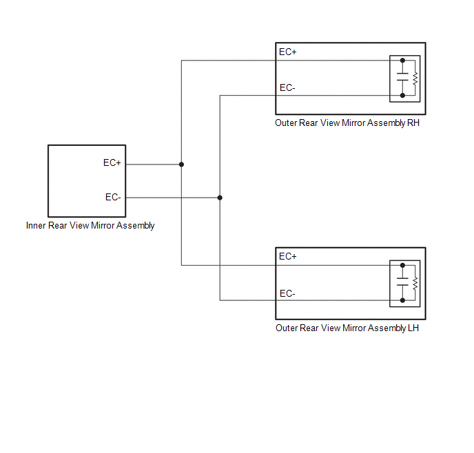
AUTOMATIC GLARE-RESISTANT EC MIRROR FUNCTION
 Communication Table
 | Sender | Receiver | Signal | Communication Method |
|---|---|---|---|
| Air Conditioning Control Assembly | Air Conditioning Amplifier Assembly | Mirror heater switch (rear window defogger switch) signal | LIN |
READ NEXT:
 System Description
SYSTEM DESCRIPTION POWER MIRROR CONTROL SYSTEM (w/o Memory) DESCRIPTION (a) This system has the following functions: electrical remote control mirror function, power retract mirror function, mirror he
How To Proceed With Troubleshooting
CAUTION / NOTICE / HINT HINT:
Use the following procedure to troubleshoot the power mirror control system (w/o Memory).
*: Use the Techstream.
PROCEDURE 1. VEHICLE BROUGHT TO WORKSHOP
Operation Check
OPERATION CHECK CHECK ELECTRICAL REMOTE CONTROL MIRROR FUNCTION (a) Turn the engine switch on (IG). (b) With L on the mirror select switch selected, check that the outer rear view mirror assembly LH s
SEE MORE:
Headlight Swivel ECU LH Communication (B2410,B2411)
DESCRIPTION Each headlight ECU sub-assembly and headlight swivel motor communicate via LIN communication. The headlight swivel motor operates according to power supplied and automatic headlight beam level control signals from its respective headlight ECU sub-assembly and sends its operating state to
Installation
INSTALLATION PROCEDURE 1. INSTALL FUEL SENDER GAUGE ASSEMBLY (a) for Type A: (1) Engage the claw to install the fuel sender gauge assembly to the fuel suction tube with pump and gauge assembly. NOTICE: Be careful not to bend the arm of the fuel sender gauge assembly. (2) Engage the 2 clamps to conne
© 2016-2026 Copyright www.lexguide.net
