Lexus ES: System Diagram
SYSTEM DIAGRAM
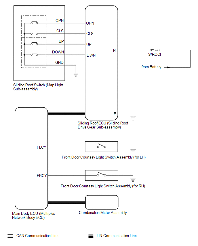 Communication Table
 | Sender | Receiver | Signal | Line |
|---|---|---|---|
| Main Body ECU (Multiplex Network Body ECU) | Sliding Roof ECU (Sliding Roof Drive Gear Sub-assembly) |
| LIN |
| Sliding Roof ECU (Sliding Roof Drive Gear Sub-assembly) | Main Body ECU (Multiplex Network Body ECU) | Sliding roof position signal | LIN |
| Combination Meter Assembly | Main Body ECU (Multiplex Network Body ECU) | Vehicle speed signal | CAN |
| Main Body ECU (Multiplex Network Body ECU) | Combination Meter Assembly | Sliding roof open warning request signal | CAN |
READ NEXT:
 System Description
SYSTEM DESCRIPTION SLIDING ROOF SYSTEM DESCRIPTION (a) The sliding roof system controls the sliding roof operation using the sliding roof ECU (sliding roof drive gear sub-assembly). Operating the slid
How To Proceed With Troubleshooting
CAUTION / NOTICE / HINT HINT:
Use the following procedure to troubleshoot the sliding roof system.
*: Use the Techstream.
PROCEDURE 1. VEHICLE BROUGHT TO WORKSHOP
NEXT
Operation Check
OPERATION CHECK CHECK AUTO OPERATION FUNCTION NOTICE:
Make sure that initialization has been completed before performing this inspection.
Click here
The sliding roof auto operation can be custo
SEE MORE:
Terminals Of Ecu
TERMINALS OF ECU CHECK WINDSHIELD WIPER MOTOR ASSEMBLY (a) Disconnect the A38 windshield wiper motor assembly connector. (b) Measure the voltage and resistance on the wire harness side connector according to the value(s) in the table below. Terminal No. (Symbol) Wiring Color Terminal Descrip
Brake Switch "A" Circuit Open (P057113)
DESCRIPTION When the brakes are applied by the dynamic radar cruise control system, the skid control ECU (brake actuator assembly) operates the stop light switch assembly (stop light control relay) to illuminate the stop lights. If the ECM receives a signal from the skid control ECU (brake actuator
© 2016-2026 Copyright www.lexguide.net
