Lexus ES: System Diagram
SYSTEM DIAGRAM
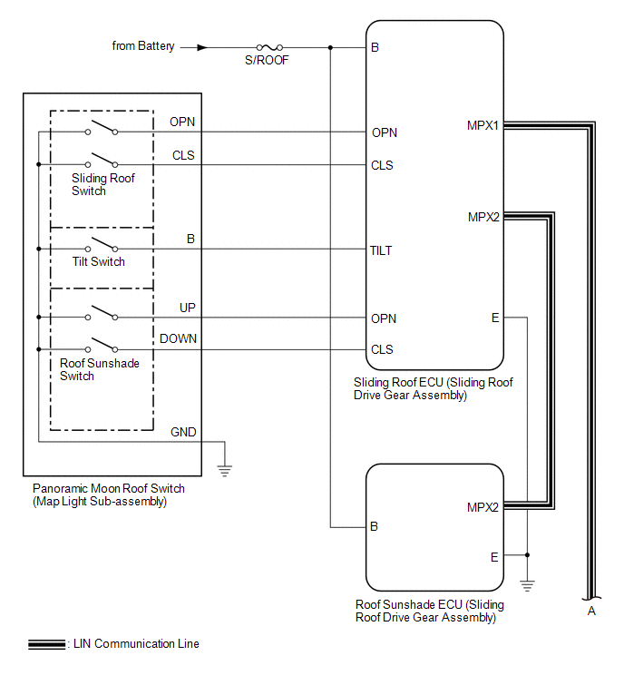
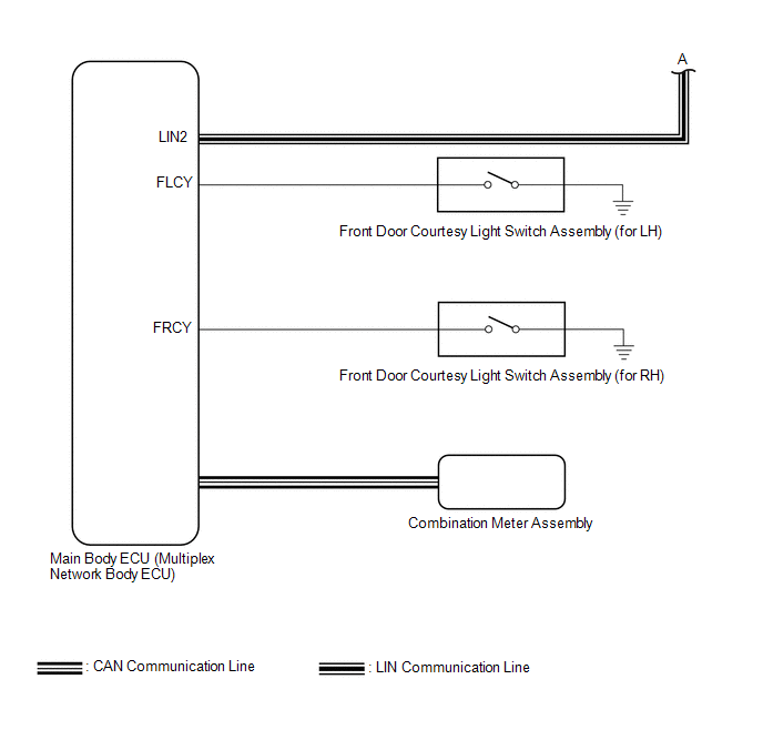 Communication Table
 | Sender | Receiver | Signal | Line |
|---|---|---|---|
| Main Body ECU (Multiplex Network Body ECU) | Sliding Roof ECU (Sliding Roof Drive Gear Assembly) |
| LIN |
| Main Body ECU (Multiplex Network Body ECU) | Roof Sunshade ECU (Sliding Roof Drive Gear Assembly) |
| LIN |
| Sliding Roof ECU (Sliding Roof Drive Gear Assembly) | Main Body ECU (Multiplex Network Body ECU) | Sliding roof glass position signal | LIN |
| Sliding Roof ECU (Sliding Roof Drive Gear Assembly) | Roof Sunshade ECU (Sliding Roof Drive Gear Assembly) |
| LIN |
| Roof Sunshade ECU (Sliding Roof Drive Gear Assembly) | Sliding Roof ECU (Sliding Roof Drive Gear Assembly) |
| LIN |
| Combination Meter Assembly | Main Body ECU (Multiplex Network Body ECU) | Vehicle speed signal | CAN |
| Main Body ECU (Multiplex Network Body ECU) | Combination Meter Assembly | Sliding roof open warning request signal | CAN |
READ NEXT:
 System Description
SYSTEM DESCRIPTION PANORAMIC MOON ROOF SYSTEM DESCRIPTION (a) The panoramic moon roof system controls the sliding roof operation using the sliding roof ECU (sliding roof drive gear assembly) and roof
How To Proceed With Troubleshooting
CAUTION / NOTICE / HINT HINT:
Use the following procedure to troubleshoot the panoramic moon roof system.
*: Use the Techstream.
PROCEDURE 1. VEHICLE BROUGHT TO WORKSHOP
NEXT
Operation Check
OPERATION CHECK CHECK AUTO OPERATION FUNCTION (FOR SLIDING ROOF) NOTICE:
Make sure that initialization has been completed before performing this inspection.
Click here
The sliding roof auto ope
SEE MORE:
Problem Symptoms Table
PROBLEM SYMPTOMS TABLE NOTICE:
After replacing the radio receiver assembly of vehicles subscribed to pay-type satellite radio broadcasts, registration of the XM radio ID is necessary (w/ SXM Function).
If the DCM (telematics transceiver) has been replaced, perform the DCM Activation procedure.
Components
COMPONENTS ILLUSTRATION *1 COOL AIR INTAKE DUCT SEAL *2 FRONT BUMPER ASSEMBLY *3 FRONT BUMPER SIDE MOUNTING BRACKET - - ILLUSTRATION *A for Bar Type Radiator Grille - - *1 FRONT BUMPER EXTENSION MOUNTING BRACKET - - ILLUSTRATION *A for Mesh Type Ra
