
Lexus ES: System Diagram
Lexus ES (XZ10) Service Manual / Vehicle Exterior / Lighting (ext) / Lighting System (for Gasoline Model) / System Diagram
SYSTEM DIAGRAM
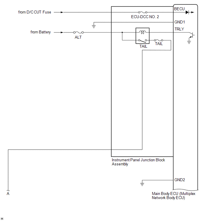
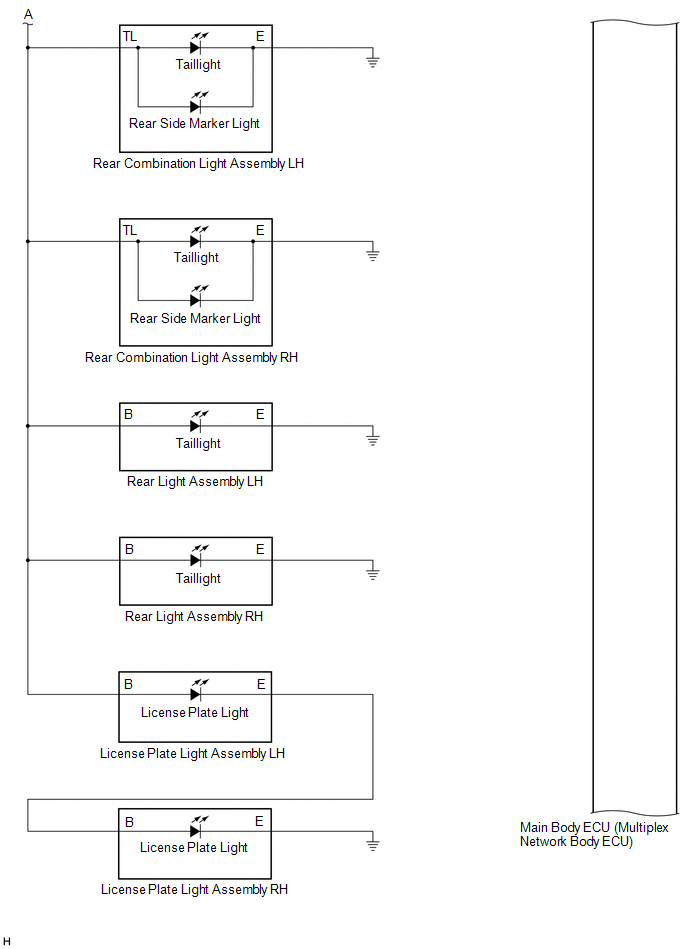
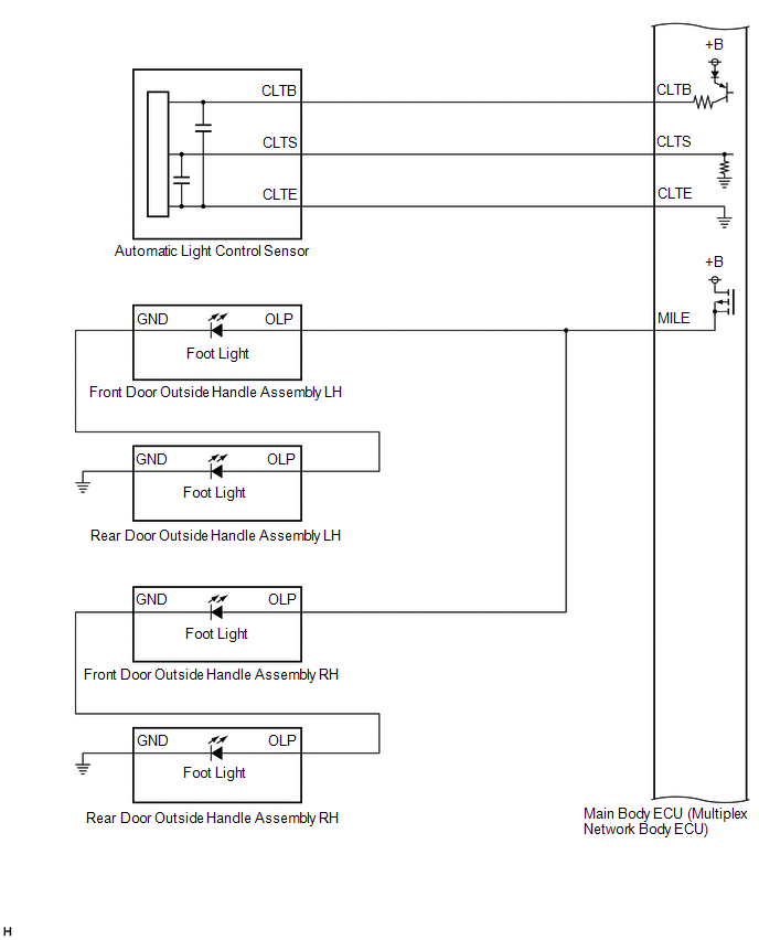
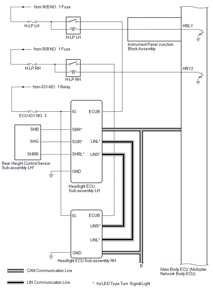
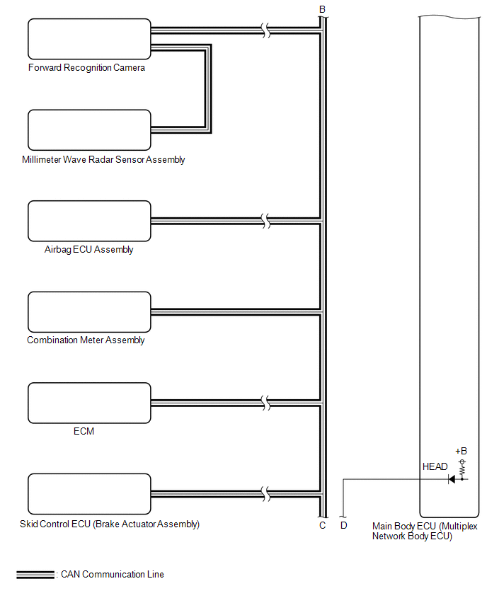
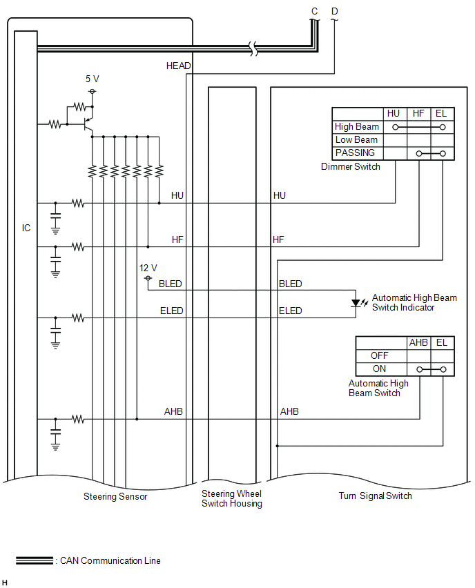
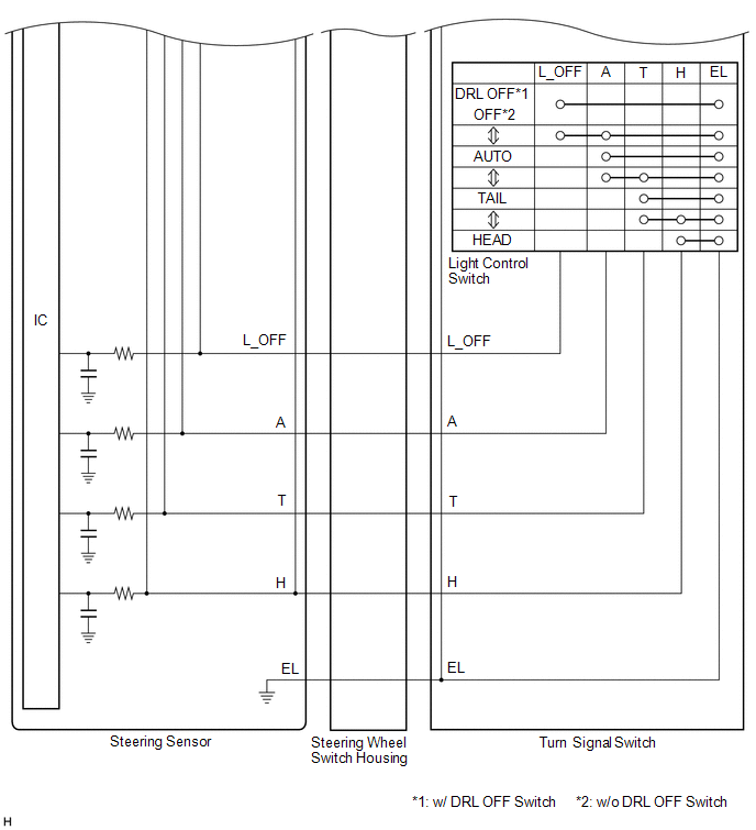
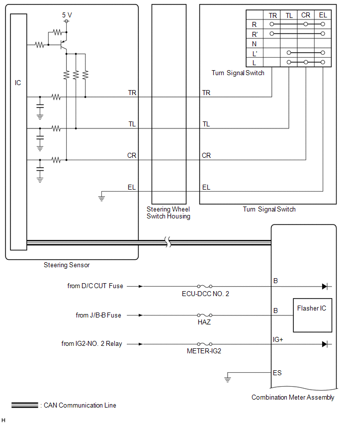
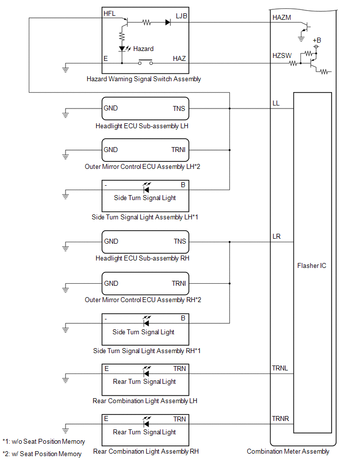
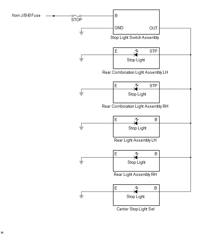
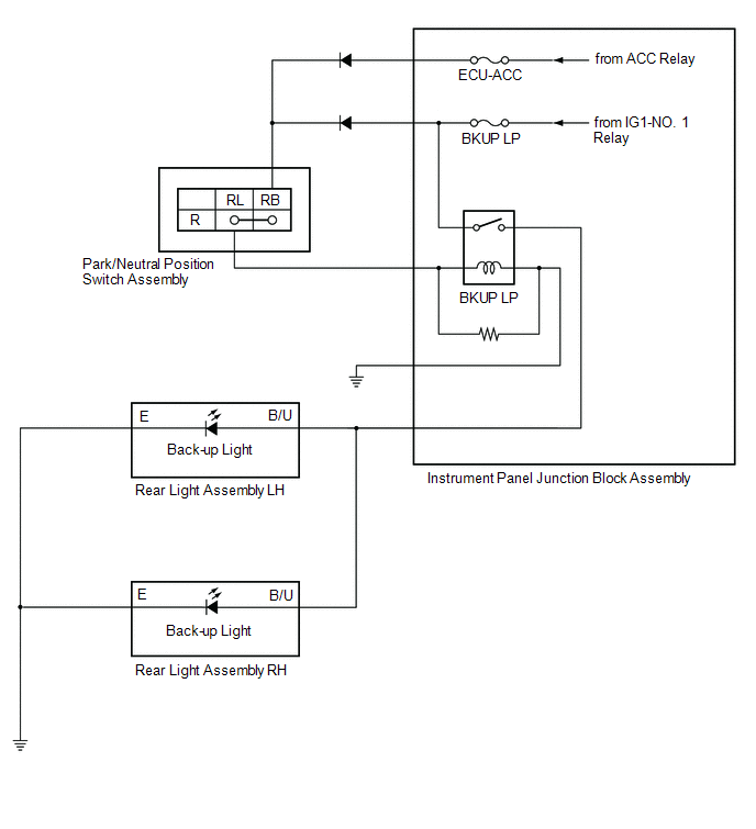
HEADLIGHT ASSEMBLY CIRCUIT (for LED Type Turn Signal Light)
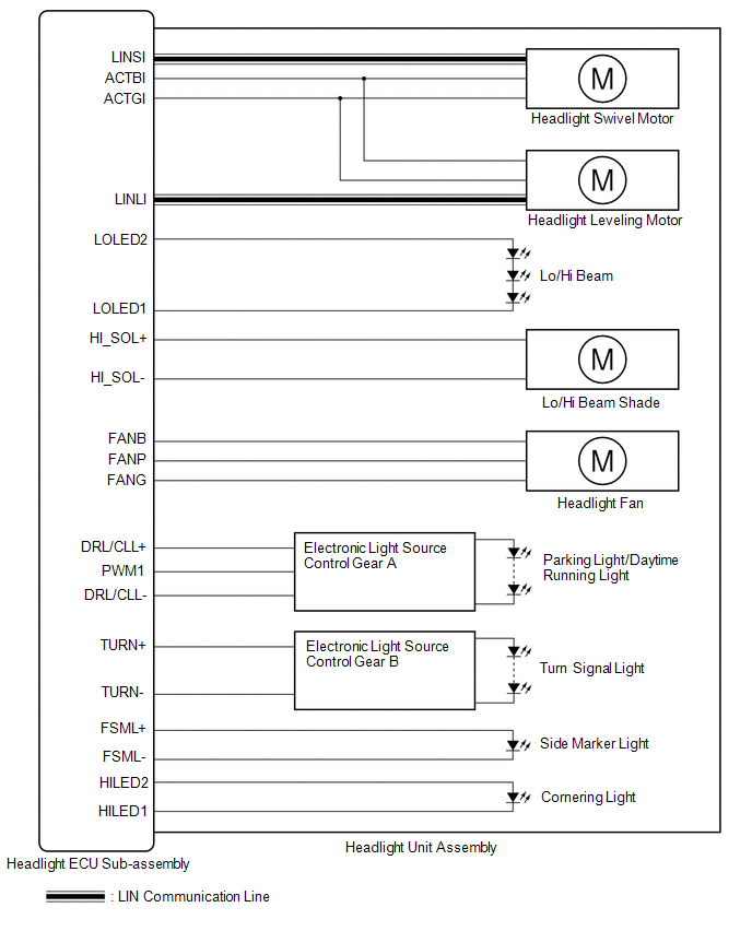
HEADLIGHT ASSEMBLY CIRCUIT (for Bulb Type Turn Signal Light) (for TMC Made)
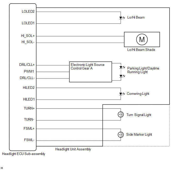
HEADLIGHT ASSEMBLY CIRCUIT (for Bulb Type Turn Signal Light) (for TMMK Made)
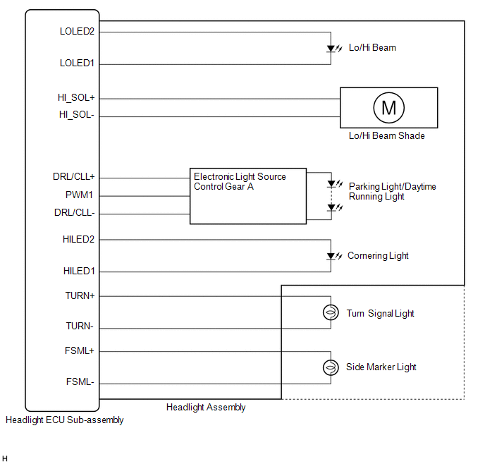
READ NEXT:
 How To Proceed With Troubleshooting
CAUTION / NOTICE / HINT HINT:
Use the following procedure to troubleshoot the lighting system.
*: Use the Techstream.
PROCEDURE 1. VEHICLE BROUGHT TO WORKSHOP
NEXT
Operation Check
OPERATION CHECK AUTOMATIC LIGHT CONTROL SYSTEM OPERATION CHECK NOTICE: Make sure that the customize settings are set to default when performing the automatic light control system operation check. Clic
Customize Parameters
CUSTOMIZE PARAMETERS CUSTOMIZE LIGHTING SYSTEM (EXT) NOTICE:
When the customer requests a change in a function, first make sure that the function can be customized.
Be sure to make a note of the
SEE MORE:
Drive Motor "A" Inverter Actuator Stuck Open (P0A7872)
DTC SUMMARY MALFUNCTION DESCRIPTION This DTC is stored when the motor generator control system is malfunctioning and current does not flow as commanded. The cause of this malfunction may be one of the following: Internal inverter malfunction
Inverter with converter assembly internal circuit malfu
Camshaft Position Sensor "B" Bank 1 Circuit Short to Ground (P036511,P036515)
DESCRIPTION The camshaft position sensor (for exhaust camshaft) (EV1 signal) consists of a magnet and MRE (Magneto Resistance Element). The exhaust camshaft has a timing rotor for the camshaft position sensor. When the exhaust camshaft rotates, changes occur in the air gaps between the timing rotor
© 2016-2026 Copyright www.lexguide.net
