Lexus ES: System Diagram
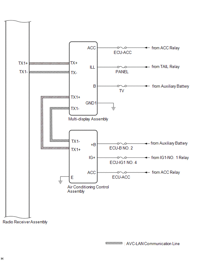
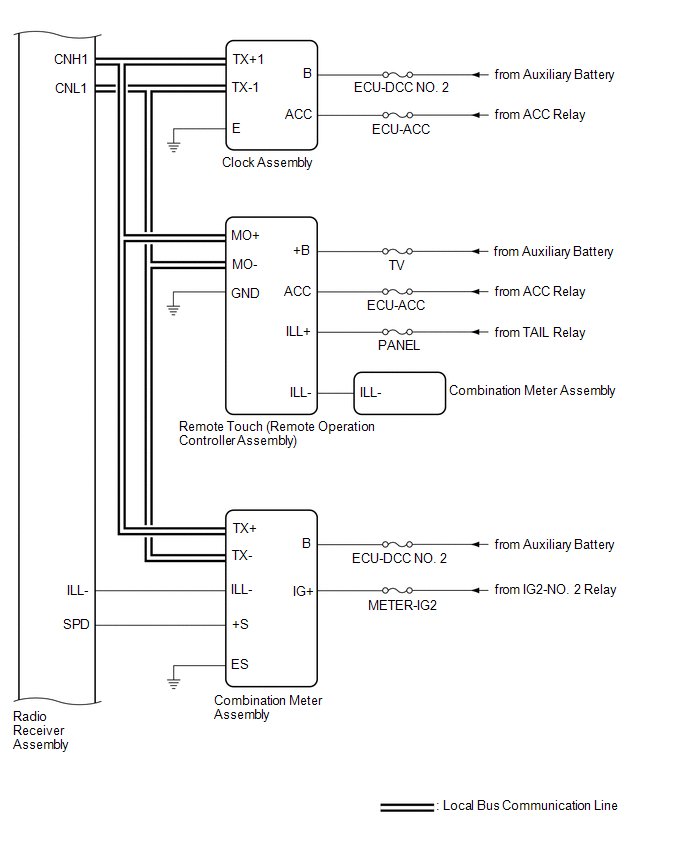
SYSTEM DIAGRAM
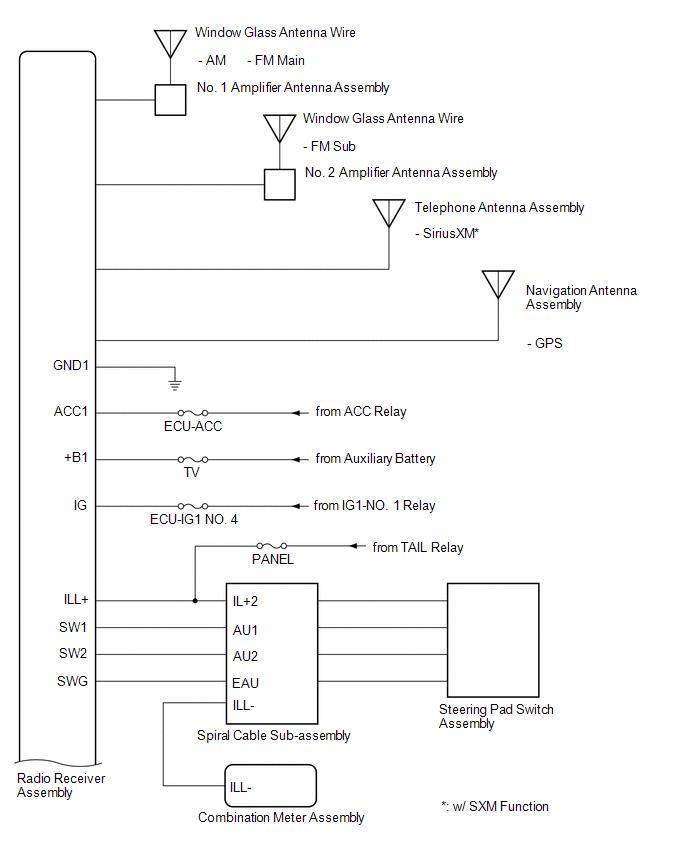
.png)
 w/ Parking Assist Monitor System
 .png) w/ Panoramic View Monitor System
w/ Panoramic View Monitor System .png)
 w/ Manual (SOS) Switch
  w/o Manual (SOS) Switch
 .png) for 10 Speakers
for 10 Speakers 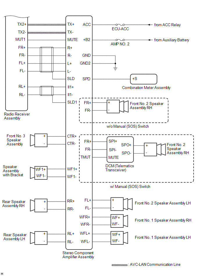 for 17 Speakers
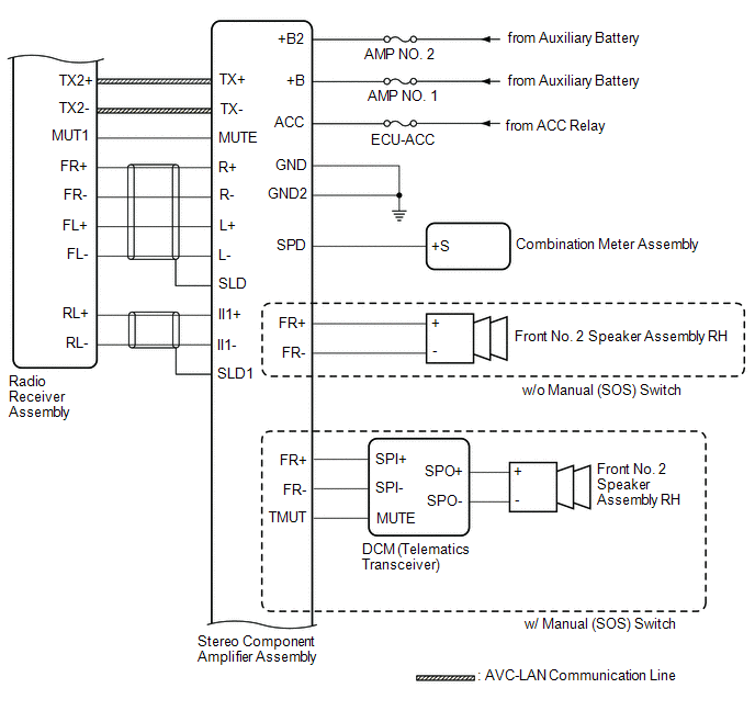
.png)
READ NEXT:
 Terminals Of Ecu
TERMINALS OF ECU HINT: Check from the rear of the connector while it is connected to the components. RADIO RECEIVER ASSEMBLY Terminal No. (Symbol) Wiring Color Terminal Description Condition
Sending Malfunction (Navigation to APGS) (U0073,U0100,U0129,U0140,U0155,U0164,U0198,U023B,U0265,U0293,U1110)
DESCRIPTION These DTCs are stored when a malfunction occurs in the CAN communication circuit. DTC No. Detection Item DTC Detection Condition Trouble Area U0073 Sending Malfunction (Navi
USB Audio System Recognition/Play Error
DESCRIPTION When a USB device or "iPod" is connected to the USB jack of the No. 1 stereo jack adapter assembly, it must have playable files. The device must also communicate with and be recognized by
SEE MORE:
Brake Switch "B" Circuit Short to Battery (P070312)
DESCRIPTION The purpose of the stop light switch signal circuit is to prevent the engine from stalling when the brakes are suddenly applied while driving in the lock-up condition. When the brake pedal is depressed, the stop light switch assembly sends a signal to the ECM. The ECM then cancels the op
Parts Location
PARTS LOCATION ILLUSTRATION *1 ECM *2 NO. 1 ENGINE ROOM RELAY BLOCK AND NO. 1 JUNCTION BLOCK ASSEMBLY - INJ FUSE *3 IGNITION COIL ASSEMBLY *4 SPARK PLUG
© 2016-2026 Copyright www.lexguide.net
