Lexus ES: System Diagram
Lexus ES (XZ10) Service Manual / Steering / Power Assist Systems / Power Steering System(for Gasoline Model) / System Diagram
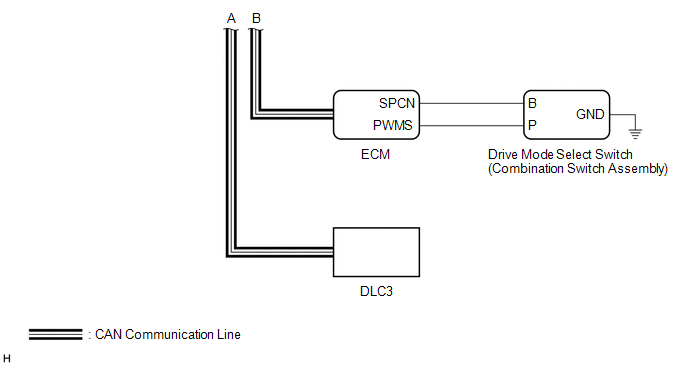
SYSTEM DIAGRAM
.png)
READ NEXT:
 System Description
SYSTEM DESCRIPTION DESCRIPTION (a) The power steering ECU (rack and pinion power steering gear assembly) generates the necessary steering assist torque by calculating the steering assist force and con
Customize Parameters
CUSTOMIZE PARAMETERS DRIVE MODE CUSTOMIZATION (w/ Adaptive Variable Suspension System) When the drive mode is switched to "CUSTOM" mode using the drive mode select switch (combination switch assembly)
How To Proceed With Troubleshooting
CAUTION / NOTICE / HINT HINT:
Use the following procedure to troubleshoot the power steering system.
*: Use the Techstream.
PROCEDURE 1. VEHICLE BROUGHT TO WORKSHOP
NEXT
SEE MORE:
Brake Pressure Control Solenoid "A" Control Circuit Short to Battery (C13C012,...,C13C049)
DESCRIPTION The ABS solenoid relay and master cylinder cut solenoid valves are built into the brake actuator assembly. Depending on the operating conditions, the master cylinder cut solenoid valves regulate the brake fluid pressure generated by the pump motor. When this DTC is stored, the fail-safe
Installation
INSTALLATION PROCEDURE 1. TEMPORARILY INSTALL NO. 4 HV BATTERY END PLATE SUB-ASSEMBLY CAUTION: Be sure to wear insulated gloves. (a) Temporarily install the No. 4 HV battery end plate sub-assembly to the HV battery with the 2 bolts and 2 nuts. (b) Fully tighten the 2 nuts. Torque: 19 N¬∑m {194 kgf¬
© 2016-2026 Copyright www.lexguide.net
