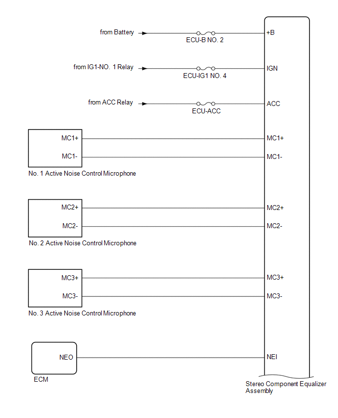
Lexus ES: System Diagram
SYSTEM DIAGRAM


READ NEXT:
 Terminals Of Ecu
TERMINALS OF ECU STEREO COMPONENT EQUALIZER ASSEMBLY Terminal No. (Symbol) Wiring Color Terminal Description Condition Specified Condition G15-1 (CANH) P CAN communication signal
 Lost Communication With ECM/PCM "A" Missing Message (U010087,U012987,U014087,U016487)
DESCRIPTION These DTCs are stored when a malfunction occurs in the CAN communication circuit. DTC No. Detection Item DTC Detection Condition Trouble Area U010087 Lost Communication With
SEE MORE:
 Inspection
INSPECTION PROCEDURE 1. INSPECT CAMSHAFT TIMING GEAR BOLT (a) Check the stroke of the plunger in the center of the camshaft timing gear bolt. Standard Stroke: 4.5 mm (0.177 in.) or more HINT: When pressing the plunger, there may be a stepped feeling. This is not a malfunction. If the result is n
 Removal
REMOVAL CAUTION / NOTICE / HINT The necessary procedures (adjustment, calibration, initialization, or registration) that must be performed after parts are removed and installed, or replaced during rear suspension member sub-assembly removal/installation are shown below. Necessary Procedures After Pa
© 2016-2026 Copyright www.lexguide.net

