Lexus ES: System Diagram
Lexus ES (XZ10) Service Manual / Brake / Parking Brake / Electric Parking Brake System (for Hv Model) / System Diagram
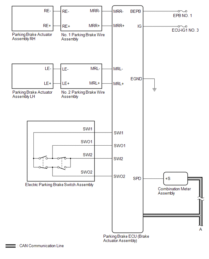
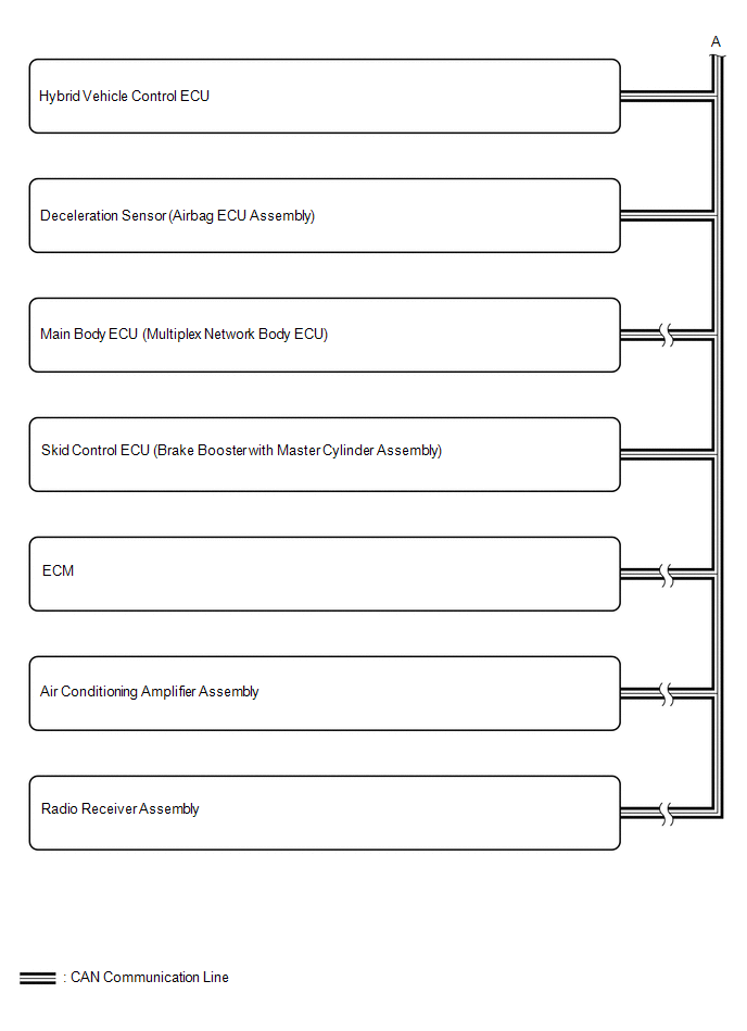
SYSTEM DIAGRAM
READ NEXT:
 Terminals Of Ecu
TERMINALS OF ECU CHECK PARKING BRAKE ECU (BRAKE ACTUATOR ASSEMBLY) *a Front view of wire harness connector (to Parking Brake ECU (Brake Actuator Assembly)) - - (a) Disconnect the A54 park
Test Mode Procedure
TEST MODE PROCEDURE *1 Rear Disc Brake Piston *2 Nut *a The nut moves inward in pad replacement mode REAR BRAKE PAD REPLACEMENT MODE HINT: When replacing the rear disc brake pad a
Control Module Communication Bus OFF (U0073,U0100,U0124,U0129,U0293)
DESCRIPTION The parking brake ECU (brake actuator assembly) communicates with the hybrid vehicle control ECU assembly, skid control ECU (brake booster with master cylinder assembly) and deceleration s
SEE MORE:
Installation
INSTALLATION PROCEDURE 1. INSTALL FRONT DRIVE SHAFT HOLE SNAP RING (a) Install a new front drive shaft hole snap ring. NOTICE: Face the end gap of the front drive shaft hole snap ring downward. 2. INSTALL FRONT DRIVE SHAFT ASSEMBLY LH (a) Coat the snap ring of the front drive inboard joint assembly
Problem Symptoms Table
PROBLEM SYMPTOMS TABLE NOTICE:
The following inspection procedures for the parking assist monitor system are based on the assumption that the audio and visual system*1 or navigation system*2 is normal. If the audio and visual system*1 or navigation system*2 has any malfunctions, first proceed wit
© 2016-2026 Copyright www.lexguide.net
