Lexus ES: System Diagram
Lexus ES (XZ10) Service Manual / Brake / Parking Brake / Electric Parking Brake System (for Gasoline Model) / System Diagram
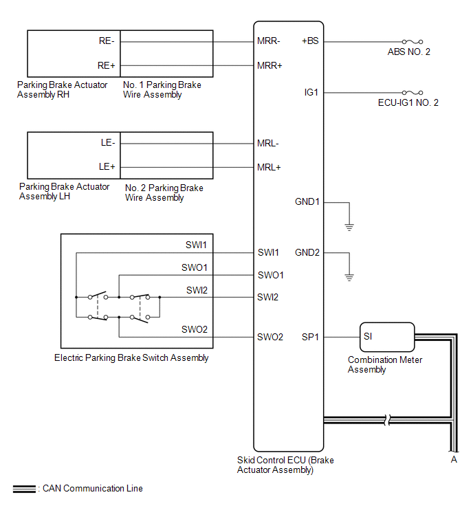
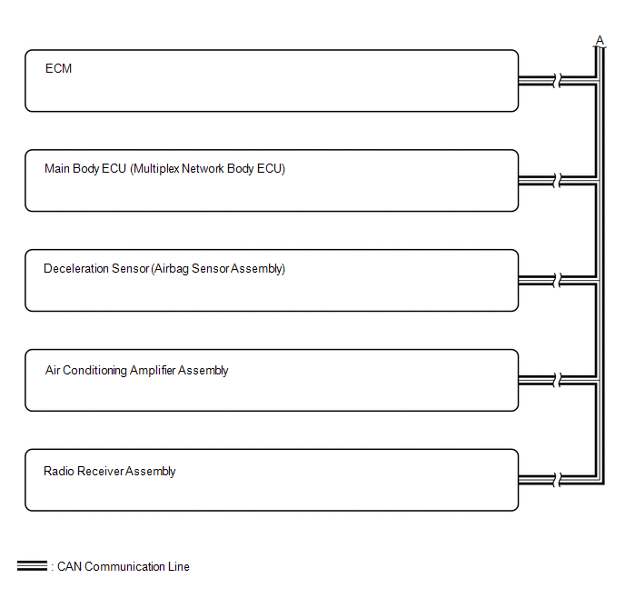
SYSTEM DIAGRAM
READ NEXT:
 Terminals Of Ecu
TERMINALS OF ECU CHECK SKID CONTROL ECU (BRAKE ACTUATOR ASSEMBLY) *a Front view of wire harness connector (to Skid Control ECU (Brake Actuator Assembly)) - - (a) Disconnect the A40 skid c
Test Mode Procedure
TEST MODE PROCEDURE REAR BRAKE PAD REPLACEMENT MODE *1 Rear Disc Brake Piston *2 Nut *a The nut moves inward in pad replacement mode HINT: When replacing the rear disc brake pad a
Vehicle Control History
VEHICLE CONTROL HISTORY DESCRIPTION
Vehicle Control History is a function that captures and stores ECU data when triggered by specific vehicle behavior.
If the customer states that the engine sta
SEE MORE:
Installation
INSTALLATION CAUTION / NOTICE / HINT HINT:
Use the same procedure for the RH side and LH side.
The following procedure is for the LH side.
PROCEDURE 1. INSTALL REAR DOOR OPENING TRIM WEATHERSTRIP (a) Align the alignment mark on the rear door opening trim weatherstrip with the flange on the v
Installation
INSTALLATION PROCEDURE 1. INSTALL SHIFT LEVER POSITION SENSOR (a) Move the shift lever to N. (b) Clean and degrease the 2 bolt holes of the hybrid vehicle transaxle assembly. (c) Temporarily install the shift lever position sensor to the hybrid vehicle transaxle assembly with 2 new bo
© 2016-2026 Copyright www.lexguide.net
