Lexus ES: Terminals Of Ecu
TERMINALS OF ECU
CHECK SKID CONTROL ECU (BRAKE ACTUATOR ASSEMBLY)
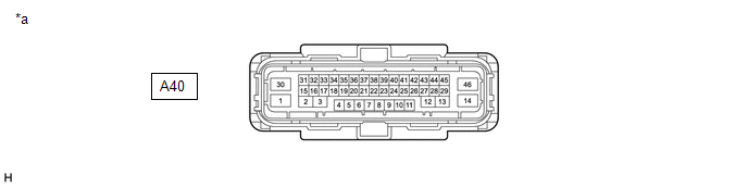
| *a | Front view of wire harness connector (to Skid Control ECU (Brake Actuator Assembly)) | - | - |
(a) Disconnect the A40 skid control ECU (brake actuator assembly) connector.
(b) Measure the voltage and resistance according to the value (s) in the table below.
| Terminal No. (Symbol) | Wiring Color | Terminal Description | Condition | Specified Condition |
|---|---|---|---|---|
| A40-30 (+BS) - Body ground | G - Body ground | Parking brake motor power supply | Always | 11 to 14 V |
| A40-36 (IG1) - Body ground | B - Body ground | IG power supply | Engine switch on (IG) | 11 to 14 V |
| A40-46 (GND1) - Body ground | W-B - Body ground | Ground | Always | Below 1 Ω |
| A40-14 (GND2) - Body ground | W-B - Body ground | Ground | Always | Below 1 Ω |
| A40-2 (MRR+) - Body ground | Y - Body ground | Parking brake motor RH (parking brake actuator assembly RH) (+) | - | - |
| A40-3 (MRR-) - Body ground | L - Body ground | Parking brake motor RH (parking brake actuator assembly RH) (-) | - | - |
| A40-13 (MRL+) - Body ground | G - Body ground | Parking brake motor LH (parking brake actuator assembly LH) (+) | - | - |
| A40-12 (MRL-) - Body ground | W - Body ground | Parking brake motor LH (parking brake actuator assembly LH) (-) | - | - |
| A40-31 (SWI1) - Body ground | P - Body ground | Electric parking brake switch assembly | - | - |
| A40-32 (SWO1) - Body ground | SB - Body ground | Electric parking brake switch assembly | - | - |
| A40-15 (SWI2) - Body ground | W - Body ground | Electric parking brake switch assembly | - | - |
| A40-16 (SWO2) - Body ground | V - Body ground | Electric parking brake switch assembly | - | - |
| A40-5 (CANH) - Body ground | Y - Body ground | CAN communication line H | - | - |
| A40-19 (CANL) - Body ground | W - Body ground | CAN communication line L | - | - |
READ NEXT:
 Test Mode Procedure
TEST MODE PROCEDURE REAR BRAKE PAD REPLACEMENT MODE *1 Rear Disc Brake Piston *2 Nut *a The nut moves inward in pad replacement mode HINT: When replacing the rear disc brake pad a
Vehicle Control History
VEHICLE CONTROL HISTORY DESCRIPTION
Vehicle Control History is a function that captures and stores ECU data when triggered by specific vehicle behavior.
If the customer states that the engine sta
SEE MORE:
Bank 1 Air-Fuel Ratio Imbalance (Port) (P11EA00,P11EC00-P11EF00,P219A00,P219C00-P219F00)
DESCRIPTION Refer to DTC P003012. Click here Refer to DTC P030000. Click here DTC No. Detection Item DTC Detection Condition Trouble Area MIL Memory Note P11EA00 Bank 1 Air-Fuel Ratio Imbalance (Port) The difference in air fuel ratios between the cylinders exceeds the thre
Front Right Microphone Circuit Component Internal Failure (B1AA696,B1AA71C)
DESCRIPTION These DTCs are stored when a malfunction occurs in the No. 2 active noise control microphone system. DTC No. Detection Item DTC Detection Condition Trouble Area B1AA696 Front Right Microphone Circuit Component Internal Failure Stereo component equalizer assembly detects
