Lexus ES: System Diagram
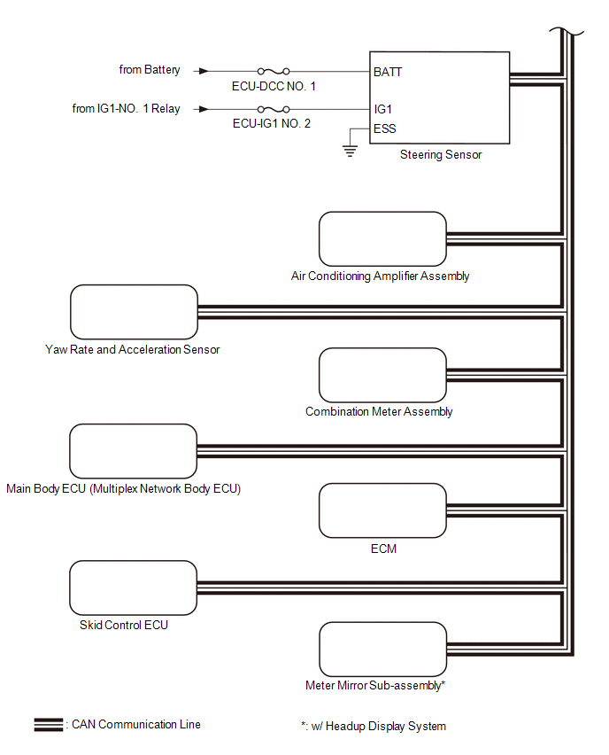
SYSTEM DIAGRAM
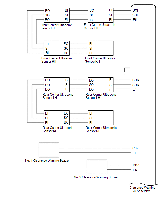
 w/ Blind Spot Monitor System
 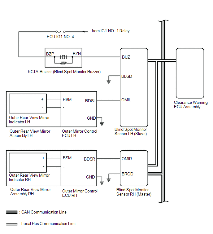 w/ Panoramic View Monitor System
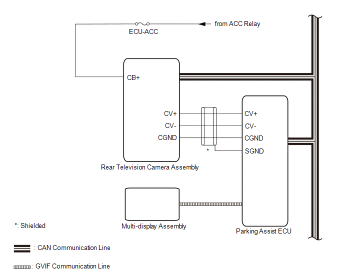
READ NEXT:
 Terminals Of Ecu
TERMINALS OF ECU CLEARANCE WARNING ECU ASSEMBLY (a) Disconnect the N41 clearance warning ECU assembly connector. (b) Measure the voltage and resistance on the wire harness side connector according to
Control Module Communication Bus "A" Off (U0073,U0100,U0124,U0126,U0129,U0140,U0155,U0164,U0265)
DESCRIPTION These DTCs are stored if there is a malfunction in the CAN communication system connected to the clearance warning ECU assembly. HINT: If CAN communication system DTCs are stored, they may
Lost Communication with Blind Spot Monitor Slave Module (U0232,U0233)
DESCRIPTION This DTC is stored when the blind spot monitor sensor LH judges that there is a communication problem with the blind spot monitor sensor RH. DTC No. Detection Item DTC Detection Con
SEE MORE:
Disassembly
DISASSEMBLY PROCEDURE 1. REMOVE FRONT BUMPER EXTENSION MOUNTING BRACKET (for Bar Type Radiator Grille) (a) Remove the 2 screws. (b) Disengage the 4 claws to remove the front bumper extension mounting bracket as shown in the illustration. Remove in this Direction 2. REMOVE FR
Main Body ECU Communication Stop Mode
DESCRIPTION Detection Item Symptom Trouble Area Main Body ECU Communication Stop Mode Any of the following conditions are met:
Communication stop for "Main Body" is indicated on the "Communication Bus Check" screen of the Techstream.
Click here
Communication stop history for "M
© 2016-2026 Copyright www.lexguide.net
