Lexus ES: Terminals Of Ecu
TERMINALS OF ECU
CLEARANCE WARNING ECU ASSEMBLY

(a) Disconnect the N41 clearance warning ECU assembly connector.
(b) Measure the voltage and resistance on the wire harness side connector according to the value(s) in the table below.
| Terminal No. (Symbol) | Wiring Color | Terminal Description | Condition | Specified Condition |
|---|---|---|---|---|
| N41-1 (IG) - N41-30 (E) | B - W-B | IG engine source signal | Engine switch off | Below 1 V |
| Engine switch on (IG) | 11 to 14 V*1 10.5 to 16 V*2 | |||
| N41-30 (E) - Body ground | W-B - Body ground | Ground | Always | Below 1 Ω |
- *1: w/o Stop and Start System
- *2: w/ Stop and Start System
(c) Reconnect the N41 clearance warning ECU assembly connector.
(d) Measure the voltage and check for pulses according to the value(s) in the table below.
| Terminal No. (Symbol) | Wiring Color | Terminal Description | Condition | Specified Condition |
|---|---|---|---|---|
| N41-4 (BOF) - N41-30 (E) | R - W-B | Power source for front sensor circuit | Engine switch off | Below 1 V |
| 11 to 14 V | |||
| N41-6 (E5) - N41-30 (E) | W - W-B | Ground for front clearance sonar | Always | Below 1 Ω |
| N41-8 (SOF) - N41-30 (E) | B - W-B | Front sensor communication signal (Front clearance sonar sensor) |
| Pulse generation (Refer to waveform 1) |
| N41-14 (CBZ) - N41-13 (EF) | LG - L | No. 1 clearance warning buzzer signal | Buzzer sounding | Pulse generation (Refer to waveform 2) |
| N41-15 (BBZ) - N41-16 (ER) | G - BE | No. 2 clearance warning buzzer signal | Buzzer sounding | Pulse generation (Refer to waveform 2) |
| N41-22 (BOR) - N41-30 (E) | LG - W-B | Power source for rear sensor circuit | Engine switch off | Below 1 V |
| 11 to 14 V | |||
| N41-23 (E1) - N41-30 (E) | GR - W-B | Ground for rear clearance sonar | Always | Below 1 Ω |
| N41-24 (SOR) - N41-30 (E) | SB - W-B | Rear sensor communication signal (Rear clearance sonar sensor) |
| Pulse generation (Refer to waveform 3) |
(e) Using an oscilloscope, check waveform 1.
(1) Waveform 1 (Reference)
| Item | Content |
|---|---|
| Measurement terminal | N41-8 (SOF) - N41-30 (E) |
| Measurement setting | 5 V/DIV., 1 ms./DIV. |
| Condition |
|
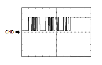
(f) Using an oscilloscope, check waveform 2.
(1) Waveform 2 (Reference)
.png)
| Item | Content |
|---|---|
| Measurement terminal | N41-14 (CBZ) - N41-13 (EF) N41-15 (BBZ) - N41-16 (ER) |
| Measurement setting | 2 V/DIV., 500 μs./DIV. |
| Condition | Buzzer sounding |
HINT:
The amplitude of the waveform changes according to the set volume.
(g) Using an oscilloscope, check waveform 3.
(1) Waveform 3 (Reference)
| Item | Content |
|---|---|
| Measurement terminal | N41-24 (SOR) - N41-30 (E) |
| Measurement setting | 5 V/DIV., 1 ms./DIV. |
| Condition |
|
COMBINATION METER ASSEMBLY
Click here .gif)
ECM
Click here
BLIND SPOT MONITOR SENSOR
Click here
REAR TELEVISION CAMERA ASSEMBLY (w/ Panoramic View Monitor System)
Click here
READ NEXT:
 Control Module Communication Bus "A" Off (U0073,U0100,U0124,U0126,U0129,U0140,U0155,U0164,U0265)
DESCRIPTION These DTCs are stored if there is a malfunction in the CAN communication system connected to the clearance warning ECU assembly. HINT: If CAN communication system DTCs are stored, they may
Lost Communication with Blind Spot Monitor Slave Module (U0232,U0233)
DESCRIPTION This DTC is stored when the blind spot monitor sensor LH judges that there is a communication problem with the blind spot monitor sensor RH. DTC No. Detection Item DTC Detection Con
CAN Communication Failure (Message Registry) (U1000)
DESCRIPTION When the clearance warning ECU assembly determines that the CAN communication circuit is malfunctioning during self diagnosis, DTC U1000 is stored. DTC No. Detection Item DTC Detect
SEE MORE:
Dcm Activation
DCM ACTIVATION HINT: If the DCM (telematics transceiver) has been replaced, it is necessary to perform the Register Vehicle Information procedure. DCM ACTIVATION (a) Connect the Techstream to the DLC3. (b) Turn the engine switch on (IG). (c) Turn the Techstream on. (d) Choose "Telematics" from the S
Components
COMPONENTS ILLUSTRATION *1 FRONT WHEEL OPENING EXTENSION PAD LH *2 FRONT WHEEL OPENING EXTENSION PAD RH *3 NO. 1 ENGINE UNDER COVER *4 NO. 2 ENGINE UNDER COVER ASSEMBLY N*m (kgf*cm, ft.*lbf): Specified torque - - ILLUSTRATION *A w/ Performance Damper - -
