Lexus ES: Steering Pad Switch Circuit
DESCRIPTION
- The steering pad switch assembly outputs the dynamic cruise control on/off signal and various control signals to the ECM.
- The ECM controls the dynamic cruise control system according to the signals received from the steering pad switch assembly.
WIRING DIAGRAM
for 2GR-FKS
.png)
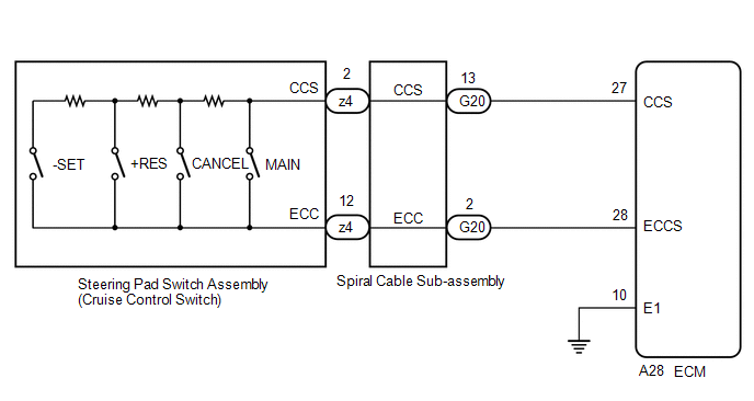
for A25A-FKS
CAUTION / NOTICE / HINT
NOTICE:
-
Before replacing the ECM, refer to Registration.
Click here
.gif)
-
The vehicle is equipped with a Supplemental Restraint System (SRS) which includes components such as airbags. Before servicing (including removal or installation of parts), be sure to read the precaution for Supplemental Restraint System.
Click here
PROCEDURE
| 1. | READ VALUE USING TECHSTREAM |
(a) Connect the Techstream to the DLC3.
(b) Turn the engine switch on (IG).
(c) Turn the Techstream on.
(d) Enter the following menus: Powertrain / Radar Cruise 1 / Data List.
(e) Read the Data List according to the display on the Techstream.
Powertrain > Radar Cruise1 > Data List| Tester Display | Measurement Item | Range | Normal Condition | Diagnostic Note |
|---|---|---|---|---|
| Cancel Switch | CANCEL switch status | ON or OFF | ON: CANCEL switch pushed OFF: CANCEL switch not pushed | - |
| -SET Switch | -SET switch status | ON or OFF | ON: -SET switch pushed OFF: -SET switch not pushed | - |
| +RES Switch | +RES switch status | ON or OFF | ON: +RES switch pushed OFF: +RES switch not pushed | - |
| Cruise Main Switch Operation Condition | Cruise control main switch status | ON or OFF | ON: Cruise control main switch pushed OFF: Cruise control main switch not pushed | - |
| Tester Display |
|---|
| Cancel Switch |
| -SET Switch |
| +RES Switch |
| Cruise Main Switch Operation Condition |
OK:
The value of each Data List item changes according to the operation of the steering pad switch assembly.
| OK | .gif) | PROCEED TO NEXT SUSPECTED AREA SHOWN IN PROBLEM SYMPTOMS TABLE |
|
.gif)
| 2. | INSPECT STEERING PAD SWITCH ASSEMBLY |
(a) Remove the steering pad switch assembly.
Click here
(b) Inspect the steering pad switch assembly.
Click here
| NG | | REPLACE STEERING PAD SWITCH ASSEMBLY |
|
| 3. | INSPECT SPIRAL CABLE SUB-ASSEMBLY |
(a) Remove the spiral cable sub-assembly.
Click here
(b) Inspect the spiral cable sub-assembly.
Click here
| NG | | REPLACE SPIRAL CABLE SUB-ASSEMBLY |
|
| 4. | CHECK HARNESS AND CONNECTOR (SPIRAL CABLE SUB-ASSEMBLY AND BODY GROUND - ECM AND BODY GROUND) |
(a) Disconnect the G20 spiral cable sub-assembly connector.
(b) Disconnect the A25 ECM connector.*1
(c) Disconnect the A28 ECM connector.*2
- *1: for 2GR-FKS:
- *2: for A25A-FKS
(d) Measure the resistance according to the value(s) in the table below.
Standard Resistance (for 2GR-FKS):
| Tester Connection | Condition | Specified Condition |
|---|---|---|
| G20-13 (CCS) - A25-41 (CCS) | Always | Below 1 Ω |
| G20-2 (ECC) - Body ground | Always | Below 1 Ω |
| G20-13 (CCS) or A25-41 (CCS) - Body ground | Always | 10 kΩ or higher |
Standard Resistance (for A25A-FKS):
| Tester Connection | Condition | Specified Condition |
|---|---|---|
| A28-27 (CCS) - G20-13 (CCS) | Always | Below 1 Ω |
| A28-28 (ECCS) - G20-2 (ECC) | Always | Below 1 Ω |
| A28-27 (CCS) or G20-13 (CCS) - Body ground | Always | 10 kΩ or higher |
| A28-28 (ECCS) or G20-2 (ECC) - Body ground | Always | 10 kΩ or higher |
| A28-10 (E1) - Body ground | Always | Below 1 Ω |
(e) Connect the A25 ECM connector.*1
(f) Connect the A28 ECM connector.*2
(g) Connect the G20 spiral cable sub-assembly connector.
- *1: for 2GR-FKS:
- *2: for A25A-FKS
| OK | | REPLACE ECM |
| NG | | REPAIR OR REPLACE HARNESS OR CONNECTOR |
READ NEXT:
 Distance Control Switch Circuit
DESCRIPTION The vehicle-to-vehicle distance control switch is used to set the distance for vehicle-to-vehicle distance control mode. The vehicle-to-vehicle distance control switch is installed in the
Cruise Main Indicator Light Circuit
DESCRIPTION When the dynamic radar cruise control system is turned on using the cruise control main switch, the cruise control indicator (vehicle-to-vehicle distance control mode) illuminates. The ECM
Cruise Main Indicator Light Circuit
DESCRIPTION When the dynamic radar cruise control system is turned on using the cruise control main switch, the cruise control indicator (vehicle-to-vehicle distance control mode) illuminates. The ECM
SEE MORE:
Diagnostic Trouble Code Chart
DIAGNOSTIC TROUBLE CODE CHART Wiper and Washer System DTC No. Detection Item DTC Output from Link B1245 Lost Communication with Wiper ECU LIN Main Body B1279 Lost Communication with Humidity/Rain Sensor LIN Main Body B1370 ECU Malfunction Windshield wiper m
Accumulator Low Pressure (C1256)
DESCRIPTION The accumulator pressure sensor is built into the brake actuator (brake booster with master cylinder assembly) and detects the accumulator pressure. The skid control ECU (brake booster with master cylinder assembly) turns on the brake warning light / red (malfunction) and brake warning l
