Lexus ES: Steering Pad Switch Circuit
DESCRIPTION
- The steering pad switch assembly outputs the dynamic cruise control on/off signal and various control signals to the ECM.
- The ECM controls the dynamic cruise control system according to the signals received from the steering pad switch assembly.
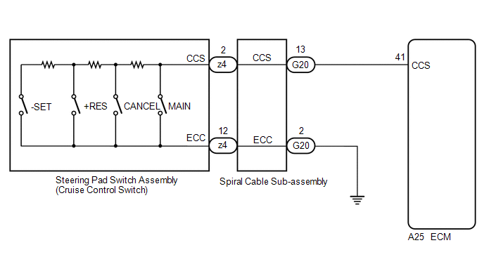
WIRING DIAGRAM
CAUTION / NOTICE / HINT
NOTICE:
-
Before replacing the ECM, refer to Registration.
Click here
.gif)
-
The vehicle is equipped with a Supplemental Restraint System (SRS) which includes components such as airbags. Before servicing (including removal or installation of parts), be sure to read the precaution for Supplemental Restraint System.
Click here
PROCEDURE
| 1. | READ VALUE USING TECHSTREAM |
(a) Connect the Techstream to the DLC3.
(b) Turn the engine switch on (IG).
(c) Turn the Techstream on.
(d) Enter the following menus: Powertrain / Radar Cruise 1 / Data List.
(e) Read the Data List according to the display on the Techstream.
Powertrain > Radar Cruise1 > Data List| Tester Display | Measurement Item | Range | Normal Condition | Diagnostic Note |
|---|---|---|---|---|
| Cancel Switch | CANCEL switch status | ON or OFF | ON: CANCEL switch pushed OFF: CANCEL switch not pushed | - |
| -SET Switch | -SET switch status | ON or OFF | ON: -SET switch pushed OFF: -SET switch not pushed | - |
| +RES Switch | +RES switch status | ON or OFF | ON: +RES switch pushed OFF: +RES switch not pushed | - |
| Cruise Main Switch Operation Condition | Cruise control main switch status | ON or OFF | ON: Cruise control main switch pushed OFF: Cruise control main switch not pushed | - |
| Tester Display |
|---|
| Cancel Switch |
| -SET Switch |
| +RES Switch |
| Cruise Main Switch Operation Condition |
OK:
The value of each Data List item changes according to the operation of the steering pad switch assembly.
| OK | .gif) | PROCEED TO NEXT SUSPECTED AREA SHOWN IN PROBLEM SYMPTOMS TABLE |
|
.gif)
| 2. | INSPECT STEERING PAD SWITCH ASSEMBLY |
(a) Remove the steering pad switch assembly.
Click here
(b) Inspect the steering pad switch assembly.
Click here
| NG | | REPLACE STEERING PAD SWITCH ASSEMBLY |
|
| 3. | INSPECT SPIRAL CABLE SUB-ASSEMBLY |
(a) Remove the spiral cable sub-assembly.
Click here
(b) Inspect the spiral cable sub-assembly.
Click here
| NG | | REPLACE SPIRAL CABLE SUB-ASSEMBLY |
|
| 4. | CHECK HARNESS AND CONNECTOR (SPIRAL CABLE SUB-ASSEMBLY - ECM AND BODY GROUND) |
(a) Disconnect the G20 spiral cable sub-assembly connector.
(b) Disconnect the A25 ECM connector.
(c) Measure the resistance according to the value(s) in the table below.
Standard Resistance:
| Tester Connection | Condition | Specified Condition |
|---|---|---|
| G20-13 (CCS) - A25-41 (CCS) | Always | Below 1 Ω |
| G20-2 (ECC) - Body ground | Always | Below 1 Ω |
| G20-13 (CCS) or A25-41 (CCS) - Body ground | Always | 10 kΩ or higher |
(d) Connect the A25 ECM connector.
(e) Connect the G20 spiral cable sub-assembly connector.
| OK | | REPLACE ECM |
| NG | | REPAIR OR REPLACE HARNESS OR CONNECTOR |
READ NEXT:
 Steering Pad Switch Circuit
DESCRIPTION
The steering pad switch assembly outputs the dynamic cruise control on/off signal and various control signals to the ECM.
The ECM controls the dynamic cruise control system according
Distance Control Switch Circuit
DESCRIPTION The vehicle-to-vehicle distance control switch is used to set the distance for vehicle-to-vehicle distance control mode. The vehicle-to-vehicle distance control switch is installed in the
Cruise Main Indicator Light Circuit
DESCRIPTION When the dynamic radar cruise control system is turned on using the cruise control main switch, the cruise control indicator (vehicle-to-vehicle distance control mode) illuminates. The ECM
SEE MORE:
Check For Intermittent Problems
CHECK FOR INTERMITTENT PROBLEMS NOTICE:
If the vehicle or vehicle controls are operated (for example, during initial inspection when the vehicle is brought in for repair) before operation history has been read and saved, the operation history information could be lost.
The operation history fun
Software Incompatibility with Body Control Module Invalid/Incompatible Software Component (U032257)
DESCRIPTION If the vehicle information stored in the forward recognition camera does not match the vehicle information sent from the main body ECU (multiplex network body ECU), the forward recognition camera stores DTC U032257. DTC No. Detection Item DTC Detection Condition Trouble Area M
