Lexus ES: Installation
INSTALLATION
PROCEDURE
1. INSTALL REAR SUSPENSION MEMBER FRONT BODY MOUNTING CUSHION (for LH Side)
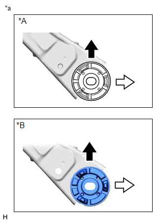
(a) Confirm the installation direction and temporarily install a new rear suspension member front body mounting cushion.
NOTICE:
- Position the rear suspension member front body mounting cushion in the correct direction.
- Do not apply lubricant to the outer sleeve of the rear suspension member front body mounting cushion.
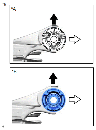
| *A | for TMC Made |
| *B | for TMMK Made |
| *a | View from Underneath |
.png) | Front of the Vehicle |
.png) | Outside of the Vehicle |
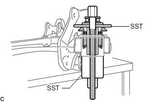
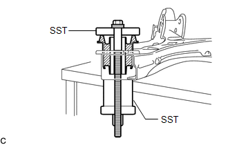
| (b) Install SST as shown in the illustration. SST: 09570-24011 SST: 09830-10010 09830-01010 09830-01020 09830-01040 09830-01050 NOTICE: Apply molybdenum grease to the threads and tip of the SST center bolt before use. |
|
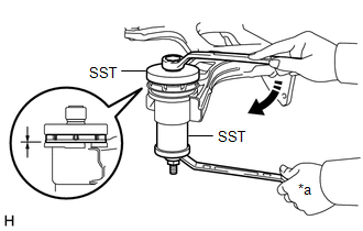
(c) Using SST, install the rear suspension member front body mounting cushion until there is no clearance between the rear suspension member sub-assembly and rear suspension member front body mounting cushion.
SST: 09570-24011
SST: 09830-10010
09830-01010
09830-01020
09830-01040
09830-01050
NOTICE:
If the rear suspension member sub-assembly is scratched, apply paint to the scratched areas of the rear suspension member sub-assembly.
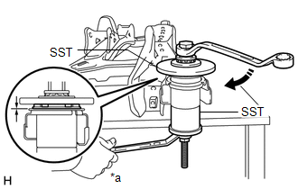
| *a | Hold |
.png) | Turn |
(d) Remove SST from the rear suspension member sub-assembly.
2. INSTALL REAR SUSPENSION MEMBER FRONT BODY MOUNTING CUSHION (for RH Side)
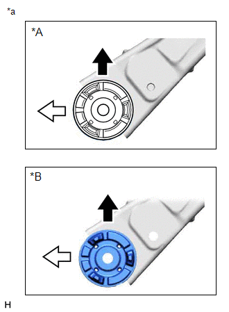
(a) Confirm the installation direction and temporarily install a new rear suspension member front body mounting cushion.
NOTICE:
- Position the rear suspension member front body mounting cushion in the correct direction.
- Do not apply lubricant to the outer sleeve of the rear suspension member front body mounting cushion.
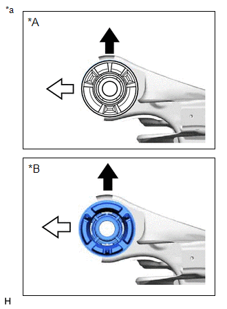
| *A | for TMC Made |
| *B | for TMMK Made |
| *a | View from Underneath |
| | Front of the Vehicle |
| | Outside of the Vehicle |
(b) Install SST using the same procedure as for the rear suspension member front body mounting cushion (for LH Side).
SST: 09570-24011
SST: 09830-10010
09830-01010
09830-01020
09830-01040
09830-01050
NOTICE:
Apply molybdenum grease to the threads and tip of the SST center bolt before use.
(c) Using SST, install the rear suspension member front body mounting cushion until there is no clearance between the rear suspension member sub-assembly and rear suspension member front body mounting cushion.
SST: 09570-24011
SST: 09830-10010
09830-01010
09830-01020
09830-01040
09830-01050
NOTICE:
If the rear suspension member sub-assembly is scratched, apply paint to the scratched areas of the rear suspension member sub-assembly.
HINT:
Perform the same procedure as for the rear suspension member front body mounting cushion (for LH Side).
(d) Remove SST from the rear suspension member sub-assembly.
3. INSTALL REAR SUSPENSION MEMBER REAR BODY MOUNT CUSHION LH
(a) Confirm the installation direction and temporarily install a new rear suspension member rear body mount cushion LH.
NOTICE:
- Position the rear suspension member rear body mount cushion LH in the correct direction.
- Do not apply lubricant to the outer sleeve of the rear suspension member rear body mount cushion LH.
| *A | for TMC Made |
| *B | for TMMK Made |
| *a | View from Underneath |
| | Front of the Vehicle |
| | Outside of the Vehicle |
| (b) Install SST as shown in the illustration. SST: 09710-28031 09711-02030 09711-02040 94622-51200 SST: 09950-60021 09951-00720 09951-00890 NOTICE: Apply molybdenum grease to the threads and tip of the SST center bolt before use. |
|
(c) Using SST, install the rear suspension member rear body mount cushion LH until there is no clearance between the rear suspension member sub-assembly and rear suspension member rear body mount cushion LH.
SST: 09710-28031
09711-02030
09711-02040
94622-51200
SST: 09950-60021
09951-00720
09951-00890
NOTICE:
If the rear suspension member sub-assembly is scratched, apply paint to the scratched areas of the rear suspension member sub-assembly.
| *a | Hold |
| | Turn |
(d) Remove SST from the rear suspension member sub-assembly.
4. INSTALL REAR SUSPENSION MEMBER REAR BODY MOUNT CUSHION RH
(a) Confirm the installation direction and temporarily install a new rear suspension member rear body mount cushion RH.
NOTICE:
- Position the rear suspension member rear body mount cushion RH in the correct direction.
- Do not apply lubricant to the outer sleeve of the rear suspension member rear body mount cushion RH.
| *A | for TMC Made |
| *B | for TMMK Made |
| *a | View from Underneath |
| | Front of the Vehicle |
| | Outside of the Vehicle |
(b) Install SST using the same procedure as for the rear suspension member rear body mount cushion LH.
SST: 09710-28031
09711-02030
09711-02040
94622-51200
SST: 09950-60021
09951-00720
09951-00890
NOTICE:
Apply molybdenum grease to the threads and tip of the SST center bolt before use.
(c) Using SST, install the rear suspension member rear body mount cushion RH until there is no clearance between the rear suspension member sub-assembly and rear suspension member rear body mount cushion RH.
SST: 09710-28031
09711-02030
09711-02040
94622-51200
SST: 09950-60021
09951-00720
09951-00890
NOTICE:
If the rear suspension member sub-assembly is scratched, apply paint to the scratched areas of the rear suspension member sub-assembly.
HINT:
Perform the same procedure as for the rear suspension member rear body mount cushion LH.
(d) Remove SST from the rear suspension member sub-assembly.
5. INSTALL REAR UPPER CONTROL ARM ASSEMBLY LH
Click here .gif)
6. INSTALL REAR UPPER CONTROL ARM ASSEMBLY RH
HINT:
Perform the same procedure as for the LH side.
7. INSTALL REAR SUSPENSION MEMBER SUB-ASSEMBLY
(a) Install the 4 rear suspension member cushions to the rear suspension member sub-assembly.
HINT:
When reusing the rear suspension member cushion, make sure to check its identification mark and install it to the correct position.
(b) Using an engine lifter and 4 attachments or equivalent tools, support the rear suspension member sub-assembly as shown in the illustration.
.png)
- The rear suspension member sub-assembly is a very heavy component. Make sure that it is supported securely.
- If the rear suspension member sub-assembly is not securely supported, it may drop, resulting in serious injury.
NOTICE:
- Use attachments or equivalent tools to keep the rear suspension member sub-assembly level.
- Keep supporting the rear suspension member sub-assembly until the installation has been completed.
.png)
| *a | Engine Lifter |
| *b | Attachment |
.png) | Attachment and Wooden Block Placement Location |
(c) Raise the rear suspension member sub-assembly until there is no clearance between the rear suspension member sub-assembly and vehicle.
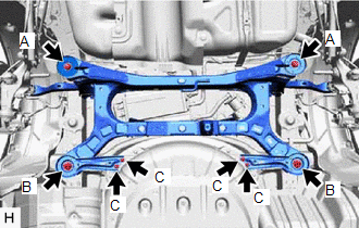
| (d) Install the rear suspension member sub-assembly with the 2 rear suspension member lower stoppers, rear suspension member lower brace LH and rear suspension member lower brace RH, 2 bolts and 6 nuts. Torque: Bolt A : 158 N·m {1611 kgf·cm, 117 ft·lbf} Nut B : 158 N·m {1611 kgf·cm, 117 ft·lbf} Nut C : 18 N·m {184 kgf·cm, 13 ft·lbf} |
|
(e) w/ Height Control Sensor:
| (1) Engage the 3 clamps to install the wire harness. |
|
.png)
8. TEMPORARILY INSTALL REAR UPPER CONTROL ARM ASSEMBLY LH
(a) Temporarily install the rear upper control arm assembly LH to the rear axle carrier sub-assembly LH with the bolt and nut.
NOTICE:
- Insert the bolt with the threaded end facing the rear of the vehicle.
- Because the nut has its own stopper, do not turn the nut. Tighten the bolt with the nut secured.
9. TEMPORARILY INSTALL REAR UPPER CONTROL ARM ASSEMBLY RH
HINT:
Perform the same procedure as for the LH side.
10. TEMPORARILY INSTALL REAR NO. 1 SUSPENSION ARM ASSEMBLY LH
Click here
11. TEMPORARILY INSTALL REAR NO. 1 SUSPENSION ARM ASSEMBLY RH
HINT:
Perform the same procedure as for the LH side.
12. TEMPORARILY INSTALL REAR NO. 2 SUSPENSION ARM ASSEMBLY LH
Click here
13. TEMPORARILY INSTALL REAR NO. 2 SUSPENSION ARM ASSEMBLY RH
HINT:
Perform the same procedure as for the LH side.
14. INSTALL REAR LOWER COIL SPRING INSULATOR LH
Click here
15. INSTALL REAR LOWER COIL SPRING INSULATOR RH
HINT:
Perform the same procedure as for the LH side.
16. INSTALL REAR COIL SPRING LH
Click here
17. INSTALL REAR COIL SPRING RH
HINT:
Perform the same procedure as for the LH side.
18. INSTALL REAR STABILIZER BAR
Click here
19. INSTALL REAR HEIGHT CONTROL SENSOR SUB-ASSEMBLY LH (w/ Height Control Sensor)
Click here
20. CONNECT REAR FLEXIBLE HOSE LH
(a) Connect the rear flexible hose LH to the rear flexible hose bracket with the bolt.
Torque:
29 N·m {296 kgf·cm, 21 ft·lbf}
21. CONNECT REAR FLEXIBLE HOSE RH
HINT:
Perform the same procedure as for the LH side.
22. STABILIZE SUSPENSION
Click here
23. INSTALL REAR STABILIZER LINK ASSEMBLY LH
Click here
24. INSTALL REAR STABILIZER LINK ASSEMBLY RH
HINT:
Perform the same procedure as for the LH side.
25. INSTALL REAR NO. 1 SUSPENSION ARM ASSEMBLY LH
Click here
26. INSTALL REAR NO. 1 SUSPENSION ARM ASSEMBLY RH
HINT:
Perform the same procedure as for the LH side.
27. INSTALL REAR NO. 2 SUSPENSION ARM ASSEMBLY LH
(a) Install the rear No. 2 suspension arm assembly LH (rear axle carrier sub-assembly side) with the bolt.
Click here
28. INSTALL REAR NO. 2 SUSPENSION ARM ASSEMBLY RH
HINT:
Perform the same procedure as for the LH side.
29. INSTALL REAR UPPER CONTROL ARM ASSEMBLY LH
(a) Install the rear upper control arm assembly LH to the rear axle carrier sub-assembly LH with the bolt.
Torque:
73 N·m {744 kgf·cm, 54 ft·lbf}
NOTICE:
Because the nut has its own stopper, do not turn the nut. Tighten the bolt with the nut secured.
30. INSTALL REAR UPPER CONTROL ARM ASSEMBLY RH
HINT:
Perform the same procedure as for the LH side.
31. INSTALL CENTER EXHAUST PIPE ASSEMBLY
for 2GR-FKS: Click here
for A25A-FXS: Click here
32. INSTALL NO. 1 FLOOR UNDER COVER (for Gasoline Model)
Click here
33. INSTALL NO. 2 FLOOR UNDER COVER (for Gasoline Model)
Click here
34. INSTALL REAR WHEEL
Click here
35. INSTALL REAR NO. 2 SUSPENSION ARM ASSEMBLY LH
(a) Install the rear No. 2 suspension arm assembly LH (rear suspension member sub-assembly side) with the nut.
Click here
36. INSTALL REAR NO. 2 SUSPENSION ARM ASSEMBLY RH
HINT:
Perform the same procedure as for the LH side.
37. INSPECT FOR EXHAUST GAS LEAK
for 2GR-FKS: Click here
for A25A-FXS: Click here
38. INSPECT AND ADJUST REAR WHEEL ALIGNMENT
Click here
39. PERFORM INITIALIZATION
for HV Model:| *1: for LED type turn signal light | |
| |
| Parking Assist Monitor System | |
| Panoramic View Monitor System | |
| Lighting System*1 | |
| *1: for LED type turn signal light | |
| |
| Parking Assist Monitor System | |
| Panoramic View Monitor System | |
| Lighting System*1 | |
READ NEXT:
 Components
COMPONENTS ILLUSTRATION *1 REAR NO. 2 SUSPENSION ARM ASSEMBLY LH *2 REAR NO. 2 SUSPENSION ARM ASSEMBLY RH *3 REAR SUSPENSION MEMBER SUB-ASSEMBLY *4 REAR UPPER CONTROL ARM ASSEMBLY
Installation
INSTALLATION PROCEDURE 1. INSTALL HOLE PLUG (a) Install the 10 hole plugs to the rear suspension member sub-assembly. HINT: There are 2 different shapes of hole plug. 2. INSTALL REAR SU
SEE MORE:
Precaution
PRECAUTION PRECAUTION FOR DISCONNECTING CABLE FROM NEGATIVE BATTERY TERMINAL NOTICE: When disconnecting the cable from the negative (-) battery terminal, initialize the following systems after the cable is reconnected. System Name See Procedure Lane Control System (for Gasoline Model)
Communication Error from VSC to ECM Invalid Serial Data Received (P163081)
DESCRIPTION The skid control ECU (brake actuator assembly) sends signals such as brake request signals to the ECM. If an abnormal signal is detected, the ECM stores DTC P163081. DTC No. Detection Item DTC Detection Condition Trouble Area MIL DTC Output from P163081 Communication E
